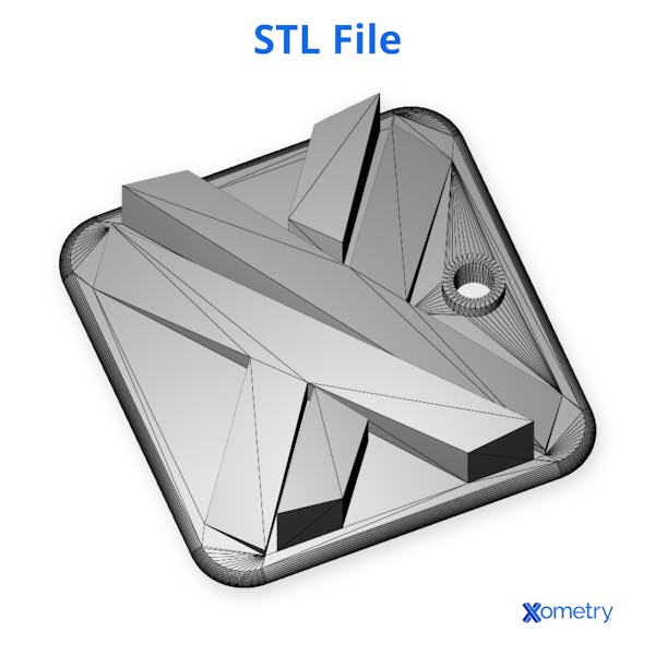
There has been some contention over what the STL file format stands for. Right from the inception of 3D printing, until this present time, several acronyms (or backronyms) have been assigned to this file format extension. An STL file is sometimes referred to as Standard Tessellation Language, Standard Triangular Language, or Stereolithography. Nonetheless, any of the above is correct and not out of place as they all bear relation to the modeling software or 3D printing technology.
An STL file describes the geometrical surface of 3D models as triangular facets. They break down or cover the surfaces of 3D models with many little triangles that connect together. This can be likened to the way a tiler covers a floor with tiles. A fancy word for this is called tessellation. There are many software applications that have been designed for the purpose of opening, viewing, or making an STL file format: Autodesk Fusion and SketchUp fall into this category.
This article will discuss STL file format, including its definition, the types of STL files, its history, and converters.

What Are STL Files?
STL files interpret the geometrical surfaces of 3D models created with the help of CAD software. Though other file formats exist, the STL format is simple to understand and use. STL files describe, interpret, or encode these surfaces in a series of small triangles, called tessellation or tiling. The complexity of the models or designs is proportional to the number of triangles used and the resolution of the 3D image. In addition, 3D STL files work hand-in-hand with the slicer software to make the job of 3D printers a reality.
Origins of the STL File Format
The use of STL files in 3D printing technology dates back to 1987. 3D Systems created the STL files for 3D printing under the authority of Chuck Hull, who was then president. The STL file was incorporated in their stereolithography (SLA) printing technology, a manufacturing technology that uses a photosensitive resin to build objects in layers. However, since the inception of STL files, the underlying principle has not changed much. It still encodes the surface geometry of objects in a standard triangle or standard tessellation language.
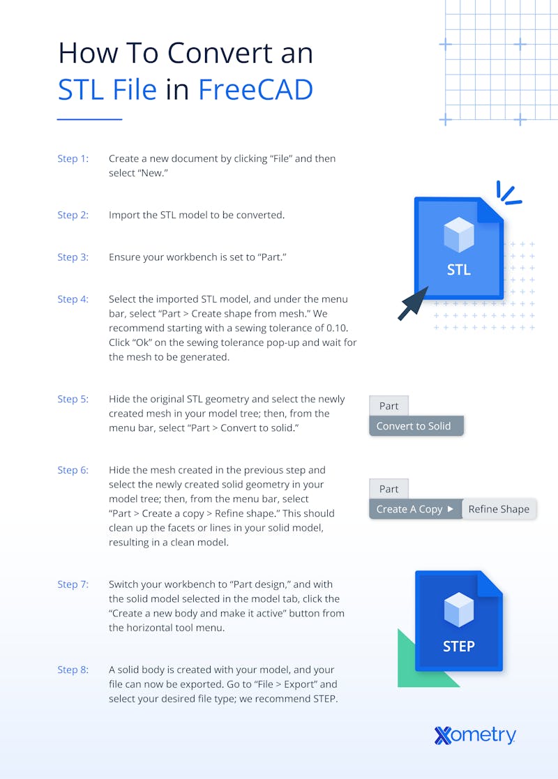
How to Convert an STL File in FreeCAD

The steps in converting an STL file depend on the software or online tool used. It is essential to follow the specific software or tool instructions. For STL file conversion to a solid or CAD model, the following steps can be followed:
- Create a new document by clicking “File” and then select “New.”
- Import the STL model to be converted.
- Ensure your workbench is set to “Part.”
- Select the imported STL model, and under the menu bar, select “Part > Create shape from mesh.” We recommend starting with a sewing tolerance of 0.10. Click “Ok” on the sewing tolerance pop-up and wait for the mesh to be generated.
- Hide the original STL geometry and select the newly created mesh in your model tree; then, from the menu bar, select “Part > Convert to solid.”
- Hide the mesh created in the previous step and select the newly created solid geometry in your model tree; then, from the menu bar, select “Part > Create a copy > Refine shape.” This should clean up the facets or lines in your solid model, resulting in a clean model.
- Switch your workbench to “Part design,” and with the solid model selected in the model tab, click the “Create a new body and make it active” button from the horizontal tool menu.
- A solid body is created with your model, and your file can now be exported. Go to “File > Export” and select your desired file type; we recommend STEP.
For more information, see our guide on how to Convert an STL File to a STEP File.
Opening an STL File
There are many ways of opening the STL file format, depending on the software or tool used. The process of opening an STL file below uses Autodesk Fusion:
- Go to the insert menu found on the design workspace and select the Insert Mesh command.
- A dialogue will open. Select the STL or mesh file.
- Select the unit type and place the model as needed.
- Orient the model as required.
It is important to note that uploading the STL or mesh file to the data panel of Fusion should be avoided. This will make reorienting the model impossible. Always import it through the Insert Mesh command.
Making an STL File
An STL file can be created by following the steps below.
1. Open TinkerCad or SketchUp, Depending on Your CAD Application of Choice.
Creating an STL file starts with CAD software, of which there are a lot of options available. There are STL files made just for beginners and those made for professionals. Depending on one's level of expertise, there are a variety of STL files to suit one's needs. Starters or beginners can go for TinkerCad or SketchUp because of their relatively simple, user-friendly interfaces. Engineers and artists alike may go for Autodesk Inventor and Blender, respectively. While some programs require payments, TinkerCad and SketchUp are free. All the user needs to do is to create an account and start—straight up—though after a good understanding of either program’s functionality.
2. Create the Model or Design With the Tools Provided by Your Software.
Once a suitable software application is downloaded, prepare the workspace. Check and familiarize yourself with the tools provided. Some tools, when used incorrectly, show an error message. With the chosen tool, an axis can be sketched and a basic 2D model drawn. It must be noted that understanding and accepting the terms and conditions of the software's cookies ensures a complete and enhanced experience.
3. Save and Export Your Design to Your Computer, After You’ve Finished.
The STL file created on the CAD software can easily be exported to the computer through the autosave feature. With this, downloading becomes unnecessary. Its purpose is also to ensure that the work remains intact. Exporting a 3D printer STL is not difficult. Locate "export" on the software's page and click on it. A box should pop up containing several options. Most software will present the user with any of these: standard triangle language, standard tessellation language, or stereolithography. They are all valid and should be chosen as the case may be.
It is important to note that all these conditions must be satisfied before exporting the file for the best result:
- Check the file or model for uniformity
- Check for holes in the mesh part
- Alter the dimensions or adjust the scale if so desired
4. Select a Slicer Program. Cura is a Good Starting Point.
Compared to other slicer programs, Cura is beginner-friendly and comes with a navigable graphical user interface (GUI). It is made by Ultimaker and is a popular software for beginners and professionals. Its function is to slice a 3D model STL file and translate it to a form that the 3D printer can interpret.
5. Open the File and “Slice” It to a G-Code File Using Your Preferred Slicing Tool.
Essentially, a G-code is a language the printer can understand and process. This is where the slicer software comes in. It does the work of transforming the STL files to a form the printer can understand and use to print the part from the model created.
Types of STL Files
There are two types of STL files: ASCII and binary STL. They are both used in encoding information about geometrical surfaces that have been triangulated or tessellated. Information is stored in both cases as the vertex coordinates and the unit normal vector components to the triangle. In most cases, it should be enough to use ASCII. But complex designs—those tiled with many small triangles—work best with the more compact binary STL file format.
Best STL File Converters
- Meshconvert: This is solely used for converting mesh files and not used for solid models or solid geometry files. Meshconvert is completely free and supports a variety of file formats.
- Online CAD Converter: This converter transforms an incredible range of file formats, but it comes at a price. Not only does it convert graphical file formats but also files that include ASM (pro/engineer) and IPT (inventor). However, a user can only convert a single file for free—anything beyond this must be paid for.
- Greentoken: This is a free online converter but supports an impressive collection of file formats, including proprietary and neutral types. Greentoken beats many free online tools because of the variety of input files it can handle.
Best Applications for STL files
- MeshLab: This software comes with a set of tools for inspecting, editing, cleaning, and converting triangular meshes. MeshLab allows the user to process raw data produced by 3D modeling programs and get it ready for printing.
- SketchUp: SketchUp is a 3D modeling tool used for several projects or drawing applications. These include landscape architecture, interior designs, and video game designs.
- SculptGL: SculptGL comes with relatively few tools. It provides a great way for quickly creating 3D models. Some of the features include setting up a digital clay before pinching, tweaking, and pushing it into shape.
Comparing STL to CAD
CAD files are used to create 3D models, while STL files are created by tiling or tessellating the models' geometrical surfaces with triangles. Put another way, an STL file is an approximated version of the CAD file.
Disclaimer
The content appearing on this webpage is for informational purposes only. Xometry makes no representation or warranty of any kind, be it expressed or implied, as to the accuracy, completeness, or validity of the information. Any performance parameters, geometric tolerances, specific design features, quality and types of materials, or processes should not be inferred to represent what will be delivered by third-party suppliers or manufacturers through Xometry’s network. Buyers seeking quotes for parts are responsible for defining the specific requirements for those parts. Please refer to our terms and conditions for more information.


