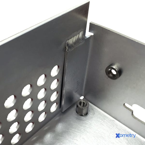
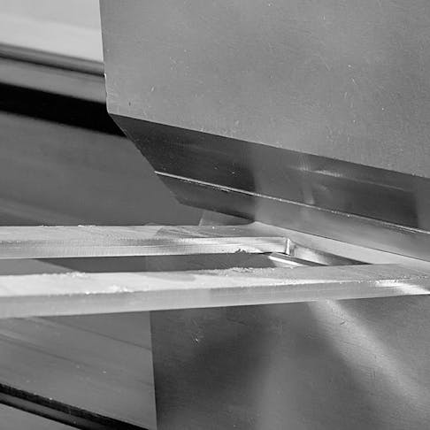
Bending is a common sheet metal operation used to create flanges, curls, and seems. Additionally, sheets with bends are stiffer than their flat counterparts. For example, a flat sheet of aluminum is less stiff than that same sheet of aluminum bent into a V cross section.

For all metals, however, there is a minimum bend radius at which the outer edge of the bend will crack. Minimum bend radii are typically specified in terms of sheet thickness (t) such as 1t, 2t, 3t, etc... We recommend a minimum bend radius of 1t for all sheet metal parts. Thus the smallest radius of any bend in a sheet should be at least equal to the thickness of the sheet. For example, if the thickness of the sheet is 1 mm, the minimum bend radius should be 1 mm.
Below is Xometry's minimum bend radius reference table which is based on theoretical sheet metal gauge thicknesses:
What is the minimum bend radius of aluminum or steel?
| Gauge | Minimum Bend Radius: Steel | Minimum Bend Radius: Aluminum |
|---|---|---|
Gauge 3 | Minimum Bend Radius: Steel 0.239 | Minimum Bend Radius: Aluminum 0.229 |
Gauge 4 | Minimum Bend Radius: Steel 0.224 | Minimum Bend Radius: Aluminum 0.204 |
Gauge 5 | Minimum Bend Radius: Steel 0.209 | Minimum Bend Radius: Aluminum 0.182 |
Gauge 6 | Minimum Bend Radius: Steel 0.194 | Minimum Bend Radius: Aluminum 0.162 |
Gauge 7 | Minimum Bend Radius: Steel 0.179 | Minimum Bend Radius: Aluminum 0.144 |
Gauge 8 | Minimum Bend Radius: Steel 0.164 | Minimum Bend Radius: Aluminum 0.129 |
Gauge 9 | Minimum Bend Radius: Steel 0.150 | Minimum Bend Radius: Aluminum 0.114 |
Gauge 10 | Minimum Bend Radius: Steel 0.135 | Minimum Bend Radius: Aluminum 0.102 |
Gauge 11 | Minimum Bend Radius: Steel 0.120 | Minimum Bend Radius: Aluminum 0.091 |
Gauge 12 | Minimum Bend Radius: Steel 0.105 | Minimum Bend Radius: Aluminum 0.081 |
Gauge 13 | Minimum Bend Radius: Steel 0.090 | Minimum Bend Radius: Aluminum 0.072 |
Gauge 14 | Minimum Bend Radius: Steel 0.075 | Minimum Bend Radius: Aluminum 0.064 |
Gauge 15 | Minimum Bend Radius: Steel 0.067 | Minimum Bend Radius: Aluminum 0.057 |
Gauge 16 | Minimum Bend Radius: Steel 0.060 | Minimum Bend Radius: Aluminum 0.051 |
Gauge 17 | Minimum Bend Radius: Steel 0.054 | Minimum Bend Radius: Aluminum 0.045 |
Gauge 18 | Minimum Bend Radius: Steel 0.048 | Minimum Bend Radius: Aluminum 0.040 |
Gauge 19 | Minimum Bend Radius: Steel 0.042 | Minimum Bend Radius: Aluminum 0.036 |
Gauge 20 | Minimum Bend Radius: Steel 0.036 | Minimum Bend Radius: Aluminum 0.032 |
Gauge 21 | Minimum Bend Radius: Steel 0.033 | Minimum Bend Radius: Aluminum 0.029 |
Gauge 22 | Minimum Bend Radius: Steel 0.030 | Minimum Bend Radius: Aluminum 0.025 |
Gauge 23 | Minimum Bend Radius: Steel 0.027 | Minimum Bend Radius: Aluminum 0.023 |
Gauge 24 | Minimum Bend Radius: Steel 0.024 | Minimum Bend Radius: Aluminum 0.020 |
Bend Orientation Rules
Another important consideration when designing sheet metal parts is bend orientation. Bends originating from the same plane should be oriented in the same direction to avoid the need of reorienting the part. This will save both money and time. Keeping a consistent bend radius across all bends will also make designs more cost-effective because the features can be produced with the same tooling and setup. Finally, it is important to note that bend accuracy increases as sheet metal thickness decreases. If bend precision is a critical requirement for your part, we recommend minimizing sheet thickness.
Become an Expert in All things Sheet Metal Fab

Disclaimer
The content appearing on this webpage is for informational purposes only. Xometry makes no representation or warranty of any kind, be it expressed or implied, as to the accuracy, completeness, or validity of the information. Any performance parameters, geometric tolerances, specific design features, quality and types of materials, or processes should not be inferred to represent what will be delivered by third-party suppliers or manufacturers through Xometry’s network. Buyers seeking quotes for parts are responsible for defining the specific requirements for those parts. Please refer to our terms and conditions for more information.

