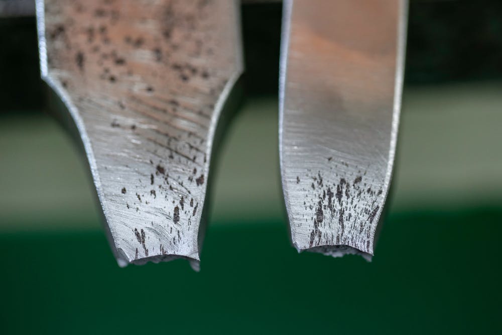
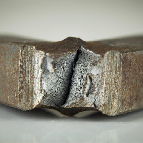
Failure by ductile fracture is an important concept to understand when designing parts that must be loaded in tension. An engineered part is generally designed so that the maximum stress the part is expected to experience remains within the elastic limit of a material, i.e. below its yield point. During ductile failure, a part will experience a localized reduction in area due to plastic deformation until it ultimately fractures. This is in contrast to brittle failure which experiences little if any reduction in the cross-sectional area before fracture.
This article will describe what ductile failure is, how it is initiated, what it looks like, as well as the various causes of ductile failure.
What Is Ductile Failure?
Ductile failure refers to the process of a material fracturing after plastically deforming past its yield limit. This is in contrast to brittle failure, where the material barely deforms before fracturing. Materials that deform in a ductile manner have a distinctive failure mode when compared to brittle failure.
The linear section of the curve between points O and A is where stress due to an applied load will not cause permanent deformation. Once stress increases beyond this limit to a material’s upper yield point (B, Figure 1), it will begin to plastically deform to the lower yield point (C, Figure 1), and the lower yield point indicates the onset of strain hardening. The cross-sectional area will continue to decrease until the stress reaches the fracture strength of the material and it fails. The term used to describe this localized reduction of area is necking, however, it must be noted that necking is not immediately present during ductile failure. A higher degree of elongation before failure means the material is more ductile. It must be noted that there will be a degree of strain hardening while the material deforms plastically.
Highly ductile materials will tend to have a less defined curve with their yield strength being defined by the 0.2% offset rule. This means that the proportional region of a material, i.e. the region where it will deform in an elastic manner is defined by a 0.2% offset. A line parallel with the linear region of the curve is drawn from 0.2% strain until it intersects with the curve where it defines the yield point.
A material’s level of ductility can be determined by the proportional reduction in cross-sectional area at the fracture plane after failure. A material with a significant reduction in the area after failure is highly ductile. Examples of this would be soft metals like aluminum or gold.
What Does “Ductile” Mean?
The word ductile comes from the Latin word ductilis, which is translated as "malleable, flexible; capable of being led." In the context of materials science, ductility refers to the ability of a material to withstand considerable plastic deformation into useful shapes without breaking or to absorb considerable energy in an as-manufactured condition before catastrophic failure occurs. For more information, see our guide on Ductility.
What Happens When Ductile Failure Occurs?
Ductile failure is a multi-step process that for the purpose of clarity will be limited to tensile ductile failure. First, the part must be loaded in tension such that the stress developed begins to exceed the elastic limit (or yield point) of the material. This is when the material will begin to plastically deform. This process is called necking and refers to the reduction in the cross-sectional area of the part. Eventually, the applied stress becomes stronger than the bonds between atoms that hold the material together. The weakest parts of the material are internal defects where the metallic crystals are not lined up for optimum strength, such as at pre-existing pores or voids, or inclusions or contaminants such as slag or metal carbides. Next, these voids will coalesce, which means they will grow and join with nearby voids to form larger voids. Once the voids have joined up to create sufficiently large discontinuities, a crack will begin to propagate outward from the initiation point until the material ultimately separates on a macro level, and fails.
What Does Ductile Failure Look Like?
Ductile fracture has a distinctive appearance. Note the reduction in the area of the part and the unique shape of the failure region. The higher a material's ductility, the more likely the necking will tend toward a sharper point, as indicated in Figure 2 below:

Tensile specimens after testing.
Image Credit: Shutterstock.com/High Simple
What Are the Causes of Ductile Failure?
Given the right combination of circumstances, any material will fail. Some of the factors that contribute to ductile failure are listed below:
1. Stress Level
Usually, a part is designed to withstand the applied load such that the stress experienced is significantly less than the yield stress by a safety factor. However, when the stress level in a part loaded in tension exceeds its yield strength, it will begin to plastically deform. This is the first stage in eventual ductile failure. The part will continue to deform until it reaches its fracture strength, at which point it will break.
2. Type of Loading
Ductile failure is most often observed in a tensile loading scenario. This means that a load is applied that would tend to stretch the material. Loading rate, which is essentially the speed with which a load is applied, can also affect the ductile failure behavior of a part loaded in tension by increasing the material’s fracture toughness. Ductile failure is a rare occurrence as the part is typically designed to handle more than the expected load.
3. Pre-Existing Cracks or Defects
Pre-existing cracks or defects weaken a material in localized areas, producing higher stress levels at those points. Under sufficient loading force, this increased stress can cause local yielding, which ultimately causes crack propagation and failure. Most ductile failures follow this mode of failure. Pre-existing voids (defects) are the initiation points for ductile failure and encourage the process of void coalescence leading to crack initiation and growth.
4. Material Properties
To eliminate ductile failure, parts must be designed such that their stress concentrations are far below the yield strength of that specific material. Medium carbon steel has a well-defined yield point, whereas highly ductile materials like aluminum have an approximate yield point that is defined at the point on the stress-strain curve where 0.2% permanent deformation is measured. This is called the "0.2% offset yield strength" which is equivalent to yield stress for highly ductile materials.
5. Environment and Temperature
Temperature can significantly affect the tensile behavior of a material. Increased temperature will lower a material’s yield point and cause the material to transition to ductile failure at significantly lower loads. Alternatively, a decrease in temperature can cause a usually ductile material to undergo a brittle fracture. The transition between ductile and brittle failure modes is defined by a material’s ductile/brittle transition temperature (DBTT). Under high loads and temperatures, materials can creep over time, this means that the material may begin to deform below its theoretical room temperature yield point. Corrosive environments can also have an effect on the failure of a material. For example, some corrosives can cause embrittlement of the material which can cause a previously ductile material to fail in a brittle manner.
How Can Ductile Failure Be Prevented?
Ductile failure can be prevented by careful engineering design. Every component and system must be designed so that the applied loads it will experience in its service environment do not exceed the material's yield point in that environment. To eliminate failure, either the load must be reduced, the cross-sectional area must be increased, or a different material must be selected.
Stress is defined as force per unit area. Either increasing the cross-sectional unit area of a part or else reducing the force on it will both result in lower stress in the part, and thus help to prevent ductile failure. Alternatively, the designer can select a material with a higher yield strength so that the load does not force the material past its elastic yield limit. It is good practice to design a part to withstand a multiple of the expected load. This multiple is called a safety factor. Many industries regulate what is considered an acceptable safety factor, and this cannot usually be chosen arbitrarily by the designer. The safety factor accounts for any potential unknowns in the service environment and in the quality of specific lots of material.
How Can Parts Which Fail By Ductile Fracture Be Repaired?
A part can be considered to have experienced ductile failure if it has undergone so much plastic deformation that it no longer performs its function, whether or not it actually breaks apart. It can only be repaired by removing the failed portion and replacing it, or by completely replacing the entire part with a new one.
This type of failure may indicate a serious design flaw: either the loads in service were higher than expected, or material too weak to bear the load was selected. In either case, a complete failure analysis should be performed to determine the cause and drive a redesign of the part to prevent future failures.
What Are the Ductile Material Examples?
The vast majority of metals used in engineering applications are ductile. Listed below are some common examples of ductile materials:
- Aluminum
- Low-carbon steel
- Zinc
- Medium-carbon steel
- Copper
- Gold
What Are the Types of Ductile Failure?
There are two general types of ductile failure, differentiated by the level of ductility of a material. These are listed below:
- Significant Necking: This refers to the situation where a highly ductile material experiences a tensile load that results in significant necking (or reduction in cross-sectional area) until failure. These materials will have a significant amount of permanent deformation before ultimately failing.
- Cup-and-Cone: This failure mode occurs when a material with a relatively lower degree of ductility fails. This ductile failure mode is caused by void nucleation and coalescence which ultimately causes crack growth and failure.
What Is the Difference Between Ductile Failure and Brittle Failure?
Ductile failure occurs when a material is loaded beyond its yield strength and begins to plastically deform for a period before ultimately failing. Brittle materials experience little or no plastic deformation before breaking. Their ultimate tensile strength and yield strength are close together. Because of the lack of plastic deformation, a brittle material gives no visual indication that it is about to fail.
Most materials fail by some combination of ductile and brittle behavior, and both strain rate and temperature can change the behavior of material from ductile to brittle, or vice versa. For more information, see our guide on Brittle Failure.
Summary
This article presented ductile failure, explained what it is, and discussed how to manage and prevent it. To learn more about ductile failure, contact a Xometry representative.
Xometry provides a wide range of manufacturing capabilities, including 3D printing and other value-added services for all of your prototyping and production needs. Visit our website to learn more or to request a free, no-obligation quote.
Disclaimer
The content appearing on this webpage is for informational purposes only. Xometry makes no representation or warranty of any kind, be it expressed or implied, as to the accuracy, completeness, or validity of the information. Any performance parameters, geometric tolerances, specific design features, quality and types of materials, or processes should not be inferred to represent what will be delivered by third-party suppliers or manufacturers through Xometry’s network. Buyers seeking quotes for parts are responsible for defining the specific requirements for those parts. Please refer to our terms and conditions for more information.

