What Is Tensile Stress?
Tensile stress is the ratio of a stretching force acting on a material to the cross-sectional area of that material. It is the force per unit area that is putting an object in tension. Tensile stress is measured in standardized material tests to indicate tensile strength—the maximum stress that a material can withstand before breaking. It is a key parameter in the selection of materials and occurs when a stretching force acts on a material, or in other words, when an object is under "tension."
When tensile stress acts on a material, there are a number of essential properties that can be calculated as a result, including:
1. Modulus of Resilience
The modulus of resilience is the amount of energy elastically stored in a material per unit volume. The resilience is calculated as the area under the curve of the tensile stress-strain curve, before the elastic limit (before the material starts to deform plastically). Resilience indicates the energy stored in a material that is under stress, as energy can be calculated as the product of force (stress) and distance (strain). The modulus of resilience is specifically per unit volume.
2. Elastic Modulus
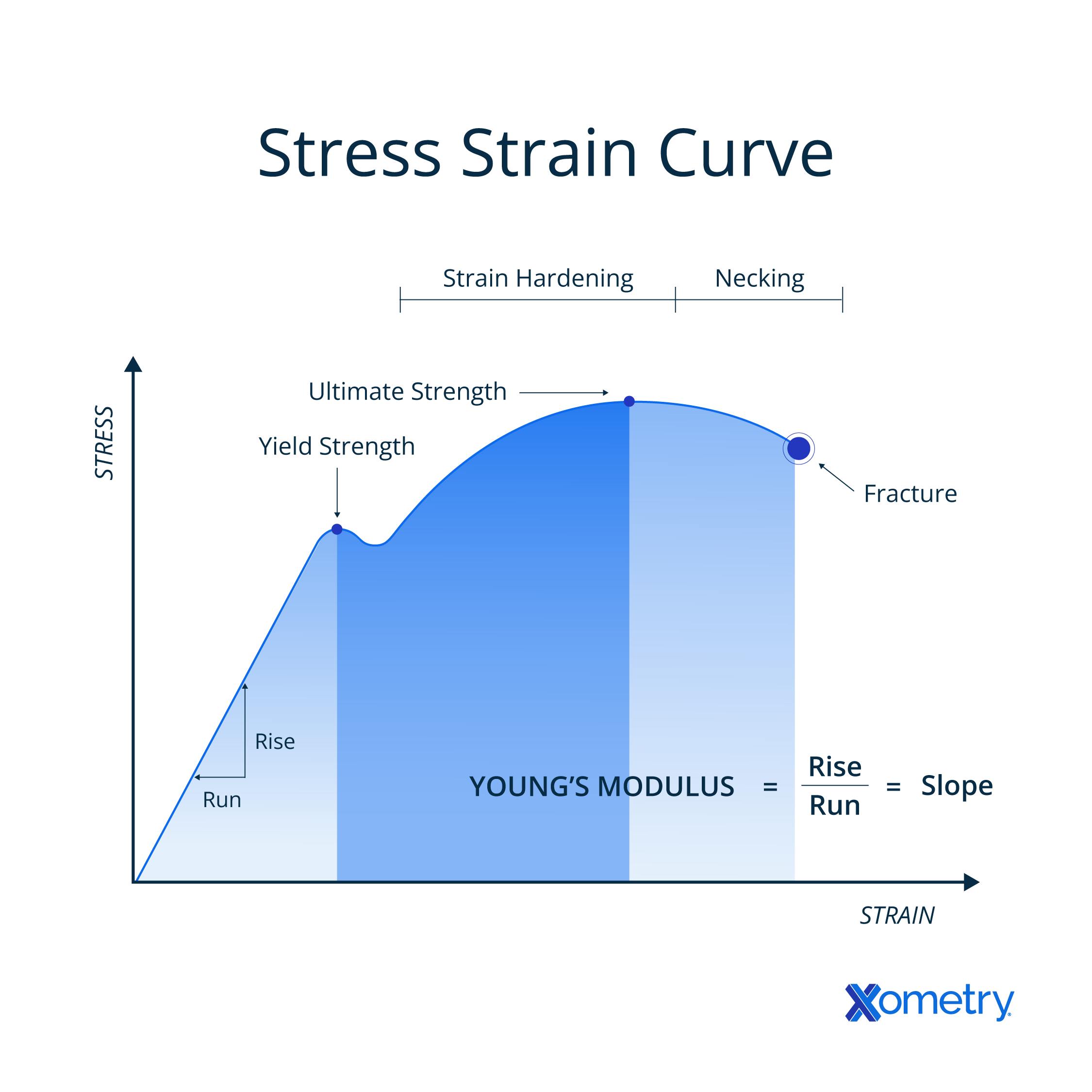
The elastic modulus also referred to as the modulus of elasticity or Young’s modulus, can be calculated by applying tensile stress to a material. The elastic modulus is the ratio between tensile stress and longitudinal strain (stretching). It is calculated as the gradient of the tensile stress curve in the elastic section. The elastic modulus infers how much strain a material will experience when subjected to a specific tensile stress.
3. Fracture Stress
Fracture stress is the tensile stress at which the material breaks (fractures). In a tensile stress test, fracture stress is the stress recorded at the end of the trial when rupture occurs. For ductile materials, the stress at fracture will be lower than the ultimate tensile stress, as necking occurs in the material sample.
4. Ultimate Tensile Stress
Ultimate tensile stress is the maximum tensile stress that a material is able to withstand before fracture. During testing (according to Hooke’s law), the stress is proportional to the strain (stretching) of a material in the elastic deformation region. As strain increases, the material begins to deform plastically (irreversibly). Maximum tensile stress will occur in the material at a point in the plastic deformation—this is the ultimate tensile stress. As strain increases past this point, the tensile stress drops until fracture.
The Formula for Tensile Stress
The formula for tensile stress is simply force over area, written as:
σ = F/A
Tensile stress is the ratio of the stretching force applied to the cross-sectional area of the material experiencing the tension.
The unit of tensile stress is the pascal (Pa). This is force over area, similar to pressure; thus, tensile stress shares units with pressure. The units can therefore also be stated as N/m2, or else as psi. Due to the magnitude of tensile strengths of common materials, the unit most commonly used is MPa (1 x 10⁶ Pa).The symbol for tensile stress is the Greek lowercase letter sigma σ, as shown above.
Understanding the Tensile Stress Curve
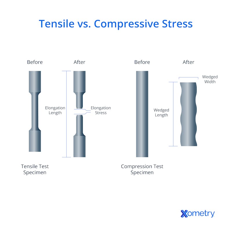
To understand the tensile stress curve, it is important for you to first learn how the curve is created. The material to be tested, in a dumbbell (or dogbone) shape, is placed into a machine that grips each end. The grips then move apart slowly, increasing the strain (displacement) of the material, and inducing stress. The strain is increased until the material breaks, and the stress is measured throughout. The relationship between stress and strain is plotted, with the constantly increasing strain on the X-axis, and the resulting stress on the Y-axis.
Second, there are key points to be identified on the tensile stress curve—refer to Figure 1 below:

The first point is the yield strength, where the material stops deforming elastically (reversibly) and starts to deform plastically (irreversibly). The gradient of the line before this point gives Young’s modulus or the modulus of elasticity. Another key point is the ultimate tensile strength, which is the highest stress recorded during the test. Then the strength at break is the measured tensile stress when the material sample finally breaks. Further, the elongation of the material can be read from the graph and can indicate whether a material is ductile or brittle.
Third, it is necessary to understand the implications of these points on a material’s practical application. The tensile stress applied to a material should never exceed its tensile strength, or else it will break. However, for most practical applications, it is preferable not to have the material deform plastically either. So generally, materials should not experience stress above their yield strength. Further, depending on the rigidity that is needed in an application, the elongation of material and stress also need to be considered—a high deformation (even elastic) may be unacceptable in many applications.
Tensile Stress and 3D Printing
Tensile stress relates to 3D printing by causing design decisions to be made during the design process that determine the tensile strength of the printed parts. The ultimate tensile strength of a 3D-printed part refers to the maximum tensile stress that the item can withstand. Depending on the intended application for a part, and its desired tensile strength, different decisions will be made while designing, choosing materials, and printing.
Some materials used for 3D printing have a higher tensile strength. The need for the part to withstand load may dictate which material is used for printing. Other parameters that can increase the tensile strength of a 3D-printed part include a higher percentage of infill and thicker layers.
Examples of Tensile Stress in the Real World
There are examples of tensile strength in everyday life including stretching a rubber band. The elongation of the rubber band is immediately seen, as well as the thinning of the cross-sectional area. If you are able to pull hard enough, you will apply a tensile stress that is greater than the ultimate tensile strength of the rubber band and it will break.
A tuned guitar string is another example of tensile stress applied to an object. Applying the correct tension to each guitar string is necessary to achieve the correct note from the vibrations of the string. Tuning a guitar adjusts the tension on each string to ensure that it produces the correct note when plucked. If the tension (tensile stress) applied is too great, the string will snap.
An engineering example of tensile stress is the thick wire cables that are used in suspension bridges. Suspension bridges specifically rely on the tensile strength of metal cables to support the load of the vehicles crossing the bridge (and the load of the bridge deck itself).

Xometry provides a wide range of manufacturing capabilities including CNC machining, 3D printing, injection molding, laser cutting, and sheet metal fabrication. Get your instant quote today.
Disclaimer
The content appearing on this webpage is for informational purposes only. Xometry makes no representation or warranty of any kind, be it expressed or implied, as to the accuracy, completeness, or validity of the information. Any performance parameters, geometric tolerances, specific design features, quality and types of materials, or processes should not be inferred to represent what will be delivered by third-party suppliers or manufacturers through Xometry’s network. Buyers seeking quotes for parts are responsible for defining the specific requirements for those parts. Please refer to our terms and conditions for more information.

