Metal stamping is a manufacturing process in which coils or flat sheets of material get formed into specific shapes through compression and shearing. Stamping encompasses multiple forming techniques such as blanking, punching, embossing, and progressive die stamping, to mention just a few. Parts use either a combination of these techniques or independently, depending on the piece’s complexity. Engineers should follow design considerations and standards like many manufacturing processes to achieve the optimal outcome. This article outlines top design standards to ensure your parts perform the best while avoiding high costs. Below is a list of the topics we will cover:
- Holes and Slots
- Bends and Forms
- Burrs
- Corner Radii
- Tabs and Notches
- Dimensions and Tolerancing

Holes and Slots
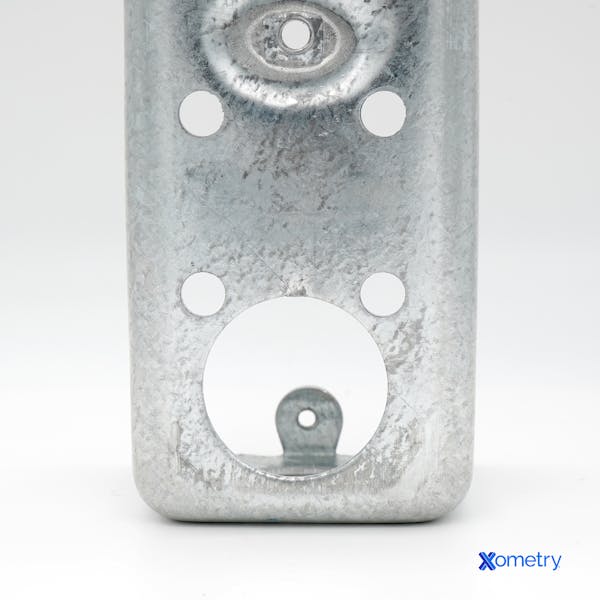
In metal stamping, holes and slots get formed via piercing techniques that use steel tools called punches. During the process, the punch compresses a sheet or strip of metal against the opening of a die. As the material begins to yield to the forces, the punch cuts through and shears the material, eventually punching all the way through as the material fully yields and breaks away at the line between the punch and die edges. The result is a hole with a burnished wall on the top face that tapers out towards the bottom, leaving a burr where the material has broken away. By the nature of this process, holes and slots will not be perfectly straight. The walls can be made uniform by using secondary machining operations; however, these can add high cost.
Minimum Diameters
The design standards for minimum diameter will depend on the chosen material. For ductile materials, such as aluminum, the minimum diameter of holes should be at least 1.2x the thickness of the material. For materials such as stainless steel alloys with higher tensile strengths, our team recommends a minimum diameter of 2x the material thickness. Slot widths should be at least 1.5x the material thickness. It is possible to achieve smaller diameters; however, they require expensive specialized processes or tooling, increasing your part cost and the risk of tool failure.
Distance From Edges
Place holes and slots near edges at a distance of at least twice the material thickness. Failure to do so may result in an outward bulging of the material web between the hole and edge. Holes closer to an edge than the recommended minimum distance may bulge or deform during stamping. These features require secondary machining or other operations that add cost.
Distance From Bends
Design holes or slots less than 0.100” in diameter or width at a distance of at least twice the material thickness (2x MT) plus the radius of the form. For holes or slots larger than this, the minimum distance should be 2.5x the material thickness plus the form radius. Holes and slots can suffer from distortion, bulging, or stretching when located closer than these recommended standards.

Bends and Forms
Bends and other formed features often come towards the end of progressive die stamping processes. Material grain direction is a crucial consideration to make when it comes to bent features. When the material’s grain is in the same direction as a bend, it is prone to cracking, especially on high-strength materials such as stainless steel alloys or tempered materials. Design bends against the material’s grain for the best results, and note grain direction on your drawing.
Bend Height
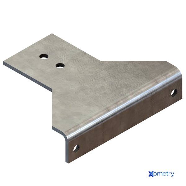
It is essential to ensure there is enough material to form bends properly. One way to provide enough material to execute a bend properly is to follow a minimum bend height standard. The recommended height of a bent feature is 2.5x the material thickness plus the bend radius. Shorter bend heights are possible but at the cost of additional operations.
Bends Close to Edges
Bent features near edges, such as bent tabs, should have an offset of material added or relief cuts in the bend. Failure to do so may result in the material tearing on either side of the bent section. When adding material offsets, you should add at least as much as the radius of the bend. Alternatively, designers can put relief notches immediately adjacent to the bend area. Relief notches should be at least twice as wide as the material thickness and as long as the bend radius, plus the material thickness.
Preventing Distortion and Bulges
Relief notches are also helpful in preventing distortion or bulging that can occur when thicker materials are bent. Bulges become especially likely with more minor bends on thicker material. Designing a relief notch on either side of the bend will help mitigate bulging. Using flag notes on your drawings is also recommended, calling attention to areas where bulging is not permissible.

Dimensioning and Tolerancing
For punched, pierced, and blanked features, dimension features from the sheared edge. Inside dimensions get measured at the shortest portion along the shear, and outside dimensions from the most extended portion. Manufacturers can achieve straight edges through secondary operations if critical features cannot tolerate edge breakaway or taper for the application; however, this adds high costs.
For formed features, designers should always give dimensions to the inside of the feature. Tolerancing of features placed on the outer end of a form should take angular tolerance of the bend – typically ± 1 degree – and the distance from the bend into account. When a feature contains multiple bends, you should consider and account for tolerance stack-up.
Other Features and Considerations
Notches and Tabs
A width of 1.5x the material thickness should be designed to prevent excessive force on punches and tabs. When made smaller, the risk of tool breakage is much greater.
Corner Radii
All corners of the blank design should include a radius of at least half the material thickness. Corners can be left relatively sharp if the material is less than 0.060” thick.
Burrs
Burrs are a typical and expected occurrence on cutout features due to how the stamping process works. The general expectation is that burrs 10% of the size of the material thickness will be present on the bottom side of cutouts. You can mitigate burrs by avoiding sharp corners and intricate cutouts. Drawing notes specifying burr direction can also help the manufacturer account for this during stamping. If your part requires burr removal, Xometry offers this as a selectable option during the quoting process.

Disclaimer
The content appearing on this webpage is for informational purposes only. Xometry makes no representation or warranty of any kind, be it expressed or implied, as to the accuracy, completeness, or validity of the information. Any performance parameters, geometric tolerances, specific design features, quality and types of materials, or processes should not be inferred to represent what will be delivered by third-party suppliers or manufacturers through Xometry’s network. Buyers seeking quotes for parts are responsible for defining the specific requirements for those parts. Please refer to our terms and conditions for more information.


