Injection molding is one of the fastest, most efficient methods of creating high-quality plastic parts—but it is not without its limitations. Designers often find defects in their parts that add lengthy delays to the manufacturing process. While frustrating, these defects are solvable given an understanding of their causes and how to implement key adjustments to the injection molding process. This article will explore one common defect known as flow marks, what they are, what causes them, and how to prevent them from occurring in your plastic injection molding capabilities.
What is a Flow Mark?
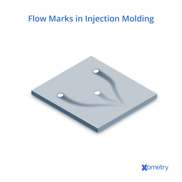
Flow marks (also known as flow lines) show as a wavy pattern or ripple on a molded part’s surface. While not detrimental to the structural integrity of a part per-se, they indicate an uneven material flow and can reduce aesthetic qualities. Flow marks occur near the plastic injection nozzle (also known as the gate) and radiate outwards through the part. As shown in the above picture, they generally appear as circles, lines, and/or repeated patterns.

What Causes Flow Marks in Injection Molding?
There are many reasons for flow marks in injection molding—but generally they are the result of the plastic material cooling at an uneven rate. There are many causes for this non-uniform cooling, so the below sections will explore material, machine, and mold/mold design causes that lead to flow marks. Note the below sections cover the most common reasons but may not cover all the possible sources.
Material Causes
Keeping track of material temperature through the injection molding machine is incredibly helpful when reducing flow marks. Thermoplastics have a Melt Flow Index (MFI) that indicates the flow characteristics of a melted plastic; plastics with a low MFI are more prone to flow marks while higher MFIs work better. This specification is closely tied to temperature, and temperature is notoriously squirrely with plastics. Too hot and the plastic will start to degrade, but too low and flow marks increase.
An improper flow rate and injection speed also cause flow marks. The injection speed should remain consistent as the plastic enters the mold, otherwise, it will slow down, cool, and cause flow marks. The flow rate should ensure the material does not lose its stored heat before entering the mold, otherwise, it will drop in temperature before molding and cause flow marks.
Machine Causes
Machine parameters are common sources of flow marks. If the machine injection pressure is too low, the material will not melt uniformly through the mold and cause uneven cooling. Similarly, low nozzle and barrel temperatures will not sufficiently heat plastic, resulting in flow issues. Improper timing also contributes to flow marks, where short residence and cycling times can cause uneven cooling and flow marks.
Mold/Mold Design Causes
Poorly designed molds are another significant source of flow marks. Molds with poor venting, non-uniform wall thicknesses, and inadequate lubricant will lead to bad results. Sprue/gate/runner design will also dictate flow mark frequency. Gates/runners that are too small or thin will reduce material flow, temperature, and pressure, causing a litany of issues including flow marks.
Another critical design consideration is a cold slug well; a cold slug is the small bit of solid plastic that cools inside the nozzle tip during cooling phases. The cold slug prevents plastic drooling during the injection process, but the slug still ends up in the molded part. Some designers will either not include a well for the cold slug to go to during injection or poorly design a cold slug well. Either case results in poor material flow and even complete blockages, causing a variety of defects.
FREE Injection Molding Design Guide
Preventing flow marks will entail some tuning, trial-and-error, and intelligent design. Below are the best ways to minimize flow marks in an injection mold, but it is vital to first isolate the cause of the flow marks before changing things up. The below sections will reference components from the above diagram.
Changes to Pressure Parameters
One of the easiest remedies is to increase the back and holding pressure of the injection molding machine. Larger back pressure will help push the fluid throughout the runners/mold, enhancing compaction. Increasing the holding pressure (or the static pressure once the plastic is injected) will improve surface quality as the plastic better conforms to the mold cavity’s finish. Note that excessive injection pressure will lead to jetting (another defect), so find a balance using other parameters.
Changes to Temperature Parameters
Temperature is not as simple—both the machine and the mold are sources of heat, and radical changes to one or the other can lead to worse defects. Temperature is also tightly related to pressure, where low melt temperatures can seem like a pressure problem at first, so take your measurements!
First, verify that the barrel temperature is to material specifications. Most thermoplastics intended for injection molding will come with recommended barrel temperatures, but operators can very slightly deviate from the recommended if needed. Also, note that there are four separate heating bands/zones: rear, center, front, and nozzle (shown in the above diagram as the three heaters around the barrel and the nozzle itself). The material temperature should be set to gradually rise as the plastic is pushed through the barrel, with a general rule of +6°C per zone.
Raising the nozzle temperature is where more trial-and-error occurs. Nozzle temperatures are ideally the same as the melt temperature, but will realistically be less due to the nozzle touching the cold mold. Raising the nozzle temperature to slightly above the melt temperature will reduce this cooling and keep the material fluid through the injection process. Again, the general rule is 6°C higher than the previous zone (the barrel front).
Finally, a too-cold mold hinders any progress with the previous temperature tweaks. Most material will come with recommended values for mold temperature but remember that cooling will naturally occur as the plastic moves further from heat sources.
For temperature in general, it is best to start with the recommended barrel, nozzle, and mold temperature, test 10 or so mold samples, examine the results, and adjust from there.
Injection Speed
Injection speed is closely tied to injection pressure—the higher the pressure, the faster the flow rate of the material. Speed is important in injection molding because, at low speeds, the molten material has more time to cool, increasing flow lines. If necessary, nozzle diameter can be increased to allow for more flow and to prevent early cooling.
Injection speed is also related to material, where a too-stiff molten polymer will slow down regardless of pressure or speed. If the molten plastic is thick and the gate is small, the filling speed will slow and cause uneven cooling. Find a material with the stiffest flow possible without causing non-fill (unfilled areas of the mold, also known as short shot), and use its recommended flow rate to ensure faster flow.
Gate, Sprue, & Runner Design
Gate, sprue, and runner design is vital—thin/small gates and runners will restrict material flow, reducing pressure, injection speed, and ultimately temperature. Luckily, simulation tools (such as C-MOLD) will calculate the ideal gate, sprue, and runner sizes for your mold to optimize the process. Gate location is also important, where gates closer to cooler or thinner areas of the mold will decrease cooling time and increase flow line frequency. Note that certain components (gears, for example) have set gate locations to improve filling, so only change entry points when there are no set rules.
Venting
Venting allows trapped air in the mold cavity to escape once the molten plastic enters the mold. Place vents at the end of each runner section and consider adding vents opposite the gate. The viscosity of the plastic will determine the vent depth, but generally, stiffer materials need deeper vents. Another benefit of computer simulations is that they will show where the melt will fill last, keying you in on where to put optimal ventilation.
Mold Design
Sharp edges/corners in cavity designs will lead to non-uniform flow and uneven cooling. Designing molds with fillet edges and round corners will improve material flow (especially to thicker areas) and reduce flow marks. Also, keep in mind the effect of wall thickness on cooling. Molds with uniform wall thickness will not have to worry about this effect, but those with variable wall thickness will experience more uneven cooling. As a rule, wall thickness should change smoothly through the part, and thicker areas should contain more fillets and round corners. A cold slug well should also be added at the end of the primary runner, preventing clogs and cooling issues.
Operator Knowledge
The last method for reducing flow marks in injection molding is to educate operators on proper procedures and on the injection molding process. If the injection molding machine is not automatically cycled, operators must understand the appropriate cycling time to prevent inconsistent molding cycles. Proper application of mold lubricant should also be taught, where large flow length-to-wall thickness ratio sections should receive more lubricant (in accordance with material specifications). Work shifting also helps reduce errors due to complacency or exhaustion, but many of the above problems can be eliminated simply by using robotics/control systems instead of human control.
Summary
This article presented an understanding of what flow marks are, what causes them, and how to prevent them in your injection molding process. If still having difficulties or not achieving the results you’d like, contact our injection molding experts at Xometry for assistance.
Xometry provides quotes on injection molding services. Visit our plastic injection molding services page to get a free, no-obligation quote or to learn more about our material capabilities, finishes, and injection mold classes. Also, be sure to review our Ultimate Guide to Injection Molding, where you can learn more about optimizing your design for the injection molding process.
Disclaimer
The content appearing on this webpage is for informational purposes only. Xometry makes no representation or warranty of any kind, be it expressed or implied, as to the accuracy, completeness, or validity of the information. Any performance parameters, geometric tolerances, specific design features, quality and types of materials, or processes should not be inferred to represent what will be delivered by third-party suppliers or manufacturers through Xometry’s network. Buyers seeking quotes for parts are responsible for defining the specific requirements for those parts. Please refer to our terms and conditions for more information.
Sources:
- Plastic Injection Molding Defects series-Flow Marks or Flow Lines (linkedin.com)
- HOW TO IMPROVE FLOW MARK IN INJECTION MOLDING - Plastic Injection Molding and Mold Maker Manufacturing (cavitymold.com)
- Flow Lines Defect in Injection Molding Process (uninko-plastics.com)
- #023 Measures to Solve Molding Defects (Flow Marks) | Technical Tutorial - MISUMI (misumi-techcentral.com)
- Flow marks Plastic injection molding defect -ECO MOLDING (injectionmould.org)
- Cold slug well design | HSmold Plastic Injection Mold for Parts in automotive, medical, industrial Mould custom Manufacturer (hsmolds.net)
- Injection Mold Flaws & How to Prevent Them: Flow Lines, Knit Lines, & Blush (chem-pak.com)
- What Causes Flow Lines in Plastic Injection Molding? - Ecomolding.com
- Don’t Forget the Cold Slug Well | Plastics Technology (ptonline.com)


