
Components of an Injection Mold
Learn about the different components of injection molding machines and what they do.

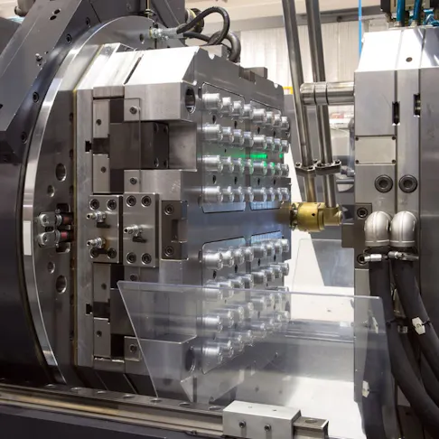
An injection molding machine is comprised of four main components: the base, the hopper, the barrel, and the clamping unit. There are also smaller components such as the nozzle, ejector pins, split mold, clamping unit, injection unit and hydraulic unit.
The base holds all the other parts and the electronics needed to run the machine. The electronics on the device have to control a range of heaters, hydraulics, sensors, and injection pressure.
Below please find the components of injection molding and how they work:
1. Hopper
The hopper is the component where the plastic material is poured before the injection molding process can begin. The hopper usually contains a dryer unit to keep moisture away from the plastic material. It may also have small magnets to prevent any harmful metallic particles from entering the machine. Next, the plastic material is poured into the following major component from the hopper, called the barrel.
2. Barrel
The barrel, or the material tube and barrel, heats the plastic material into a molten state to let plastic flow through the barrel. The screw inside injects the plastic into molds or cavities in the clamping unit. Therefore, the temperature in the barrel needs to be adequately regulated to maintain the appropriate temperature for different types of plastic material. The function of the cylinder is to transport, compact, melt, agitate and press the plastic before it reaches the injection mold.
3. Screw Motion or Reciprocating Screw
Reciprocating screws were created in the mid-1950s, and by 1960 they quickly began to replace the older systems. The advantage of the reciprocating screw design is that it helps manage the temperature of the molten plastic.
The screw moves plastic through the barrel. First, as the pellets are fed from the hopper into the barrel, the screw is rotated, driving the material forward while more pellets are added. Second, the flights provide a continuous mixing action that distributes heat evenly throughout the mass. This mixing also helps to purge the mechanism of different materials and any colors left behind from an earlier production runs on the same injection molding machine.
The reciprocating screw is responsible for providing most heat to the thermoforming plastic. This is because the diameter of the screw decreases as it approaches the tip. As a result, plastic pellets are pulled along by the flights, compressed into a tighter space, and cut by turning flights. This action creates friction that mixes the pellets uniformly and heats them to the proper temperature.
FREE Injection Molding Design Guide
4. Heaters
An injection molding machine can have different types of heaters for maintaining temperatures in conduits and nozzles and heating molds and platens. A heating element can be attached to the barrel and used to melt the hopper's molding material to become liquified material. Some of the different types of injection molding heaters include band heaters, coil/nozzle heaters, cartridge & strip heaters, and insulated cloth heating jackets.
5. Nozzle
The nozzle is an injection molding component located at the bottom of the machine’s ejector system. It pushes liquified plastic out of the barrel and into the mold. The nozzle rests against a surface on the mold called the sprue bushing and locating ring, which helps center the nozzle on the mold. Today, nozzles can provide a variety of functions, including filtering, mixing, and shut-off of melt flow.
Nozzle filters can minimize the clogging of gates and hot runner tips from foreign material or contamination in the melt stream. Mixing nozzles can enhance the dispersion and mixing of additives, improving molded part quality while reducing the volume and cost of additives. Shut-off nozzles can reduce drool in injection molding operations where the press is frequently disengaged from the mold, such as in many two-shot molding applications.
6. Extraction Pins or Ejector Pins
Ejector pins are vital in creating parts. They are an essential component of the ejection system in molds, which determines the outcome of products in an injection molding process.
The metal injection mold comprises two parts: A and B sides. After the molten material in the mold is cooled, both parts are separated to remove the solid plastic. Injection molds are built so that when they are opened, the A-side half is lifted, leaving the formed part and the B-side.
Extraction pins are found on the B-side half of the injection mold, where they push the formed part out of the mold (or extract it). The pin mark is commonly imprinted on finished products as a dent.
There are many types of ejector pins. Through-hard ejector pins are heat-treated to ensure consistency in the hardness through the diameter of the pin. A case hardened ejector pin is much harder than the through-hard pins and is suitable for die casting ejection systems. A black ejector pin is coated with a black surface treatment, allowing it to self-lubricate and withstand high temperatures up to 1000°C.
7. Split Molds
In injection molding, a parting line is where two halves of a mold meet when closed, especially on a split mold. The plastic product created by the injection mold is divided into two parts, and the line separating the two mold haves are called parting lines. Split molds are one type of injection mold, where the jaws form the mold cavity. The jaws are injected diagonally on the nozzle side and are then moved on the diagonal to the outside when the mold opens with a pull tab. Then the injection molded part is released.
The jaws can also be guided on the ejector side. They are then moved, during or after opening the mold, mostly with hydraulic cylinders or mechanically using springs or air.
8. Clamping Unit
The purposes of the clamping unit are to open and close an injection mold and eject the injection-molded products. The two main types of clamping systems are the hydraulic and toggle configurations. The hydraulic clamp system has one or more hydraulic cylinders, while the toggle clamp system has a series of linkages.
The clamping unit has two large clamping plates that hold the injection mold. A mold consists of two steel parts attached to each of the large plates on the clamping unit. When the machine is ready to inject plastic into the mold or cavity, the clamping unit closes the two independent plates. It lets the plastic flow into the cavity to create the part. The plastic component is then cooled into a solid. Once the plastic is cool enough, the clamping unit opens the injection mold, and the part falls out of the mold halves and is collected in a bin.
Other components of the clamping unit include machine ejectors, a moveable platen, a stationary platen, and tie bars.
9. Injection Unit
A central component of injection molding machines is the injection unit, which comprises other parts. The injection unit's purpose is to melt the raw material and guide it into the mold. The injection unit consists of the hopper, the barrel, and the screw. The polymer granules are first dried and placed in the hopper, then mixed with the coloring pigment or the other reinforcing additives.
The granules then feed into the barrel, where they are simultaneously heated, mixed, and moved towards the mold by the screw motion. The screw and barrel have the same geometry, optimized to help build up the pressure to the correct levels and melt the material.
10. Hydraulic Unit
A hydraulic system or unit is crucial in plastic injection molding machines. The system may be running continuously during production cycles. Nozzle approach, injection of the plunge screw, extruder screw rotation, plus the closing of the mold require a significant number of motion-activated sub-circuits. Granular plastic material requires a highly steady motion to move smoothly through the heated plasticized state as it flows into the mold during the screw rotation and plunge phase. The quality of the injection molded product could be compromised if the hydraulic motions cause any irregularities.
A necessity for force control sub-circuits also exists to keep the mold from opening and to hold nozzles in place along the sprue of the injection mold. During injection molding, these functions are critical. Adjusting and monitoring hydraulic pressure controls the mechanical pressure.
The mechanism for the screw, which is moved by the hydraulic motor, coupled with the cylinder that propels the screw forward, makes up a complex mechanism that requires exacting hydraulic seals during the injection and packing process of the mold. However, improvements in modern seal technology produce leak-free hydraulic machines suitable for molding plastic products that can even be used in the medical and food industries.
How Does the Process of Injection Molding Work?
The injection molding process works by adding plastic pellets or metal powder to the injection molding machine’s hopper. Next, the hopper pours the plastic into the barrel, where it is heated into a liquid form. The molten plastic or metal enters the mold from the barrel through the nozzle.
A nozzle in the extruder presses tightly into a recess in the stationary half of the mold. The two halves of the mold, with a vertical parting surface, are made from heavy steel and mounted on thick steel tie-bars. Within the injection mold is a system of runners that distributes melt from the sprue to the mold cavities that determine the dimensions of the molded product. Using clamp plates, the mold halves clamp together with high pressure from a hydraulic piston.
Cooling channels passing near the cavities keep the mold cold, well below the solidification range of the plastic or other material. Next, the screw moves forward, forcing the melt through the runners and into the cavities, and maintains melt pressure (5,000-15,000 psi, 34-103 MPa) while the newly injection molded part cools and solidifies.
Then, the far half of the injection mold is withdrawn, activating ejector pins that push the molded part and runners out of the mold halves. At the same time, the extruder retracts and generates more hot melt.
Typically, the process is mostly automated with computer controls. Injection machines are rated by their melting capacity, shot size, and clamping force. They range from machines shooting two ounces of melt into a family mold that makes the parts for a hobbyist’s model airplane to machines that can mold 40-gallon trash cans in injection molds with two cavities—one for the can, the other for its lid. Injection-molded parts come in many shapes and sizes, meaning mold components come in various types.
How to Maintain the Parts of Injection Molding Machine
The maintenance of injection molding machines should look at the surface and go deep into the root of the equipment so that the maintained equipment can stay operational and not introduce errors or defects in the molded products from a production run.
The mechanical hinge of the clamping unit has a long service life. Still, each movable part should be adequately lubricated because otherwise, the mechanical hinge will wear and reduce its service life. The four coring columns should be kept clean, along with the moving formwork's sliding feet and sliding rails.
The clamping unit shouldn’t be used close to or in excess of the working pressure. The clamping stroke should be controlled at a more appropriate position to reduce the impact on the machine during clamping.
The injection platform’s guide rod should be kept lubricated and clean, and the surface of the injection platform clean and dry. Nothing except plastics, pigments, and additives should be put into the hopper. Before using special plastics, the plastic supplier should be consulted to determine which injection screw is most suitable for that type of plastic.
The relevant methods provided by the plastic manufacturer should be used to replace the plastic correctly and clean the melt cartridge, as well as to periodically check all parts of the shooting table, tighten the loose parts, and ensure that the installation balance of the two injection cylinders is correct.
To avoid oil leakage and wear of the cylinder pump core caused by the damage to the oil seal of the injection cylinder, the lubricating grease of the beer bell combination of the oil pressure motor should be regularly discharged and replaced with fresh lubricant. When the melt temperature is normal, and there are melt black spots or discoloration, the injection molding screw may be damaged, so this should be checked.
It is essential to maintain the machines used for injection molding to avoid costly repairs or generating inferior injection molded parts.
For more information see our guide on maintaining injection molds.
Summary
This article provided a look at the different components of injection molding machines, what they do, and how they operate.
About Xometry
Xometry offers a full range of injection molding capabilities to help with your production needs. Visit our website to explore the full range of our capabilities or to request a free, no-obligation quote.
Disclaimer
The content appearing on this webpage is for informational purposes only. Xometry makes no representation or warranty of any kind, be it expressed or implied, as to the accuracy, completeness, or validity of the information. Any performance parameters, geometric tolerances, specific design features, quality and types of materials, or processes should not be inferred to represent what will be delivered by third-party suppliers or manufacturers through Xometry’s network. Buyers seeking quotes for parts are responsible for defining the specific requirements for those parts. Please refer to our terms and conditions for more information.