For high-volume production of plastic parts, the valve gate injection molding technique can make high-quality items for many industries, including medical and cosmetic. We’ll explore why the humble valve gate is so important to this process and how it works.
What Are Valve Gates for Injection Molding?
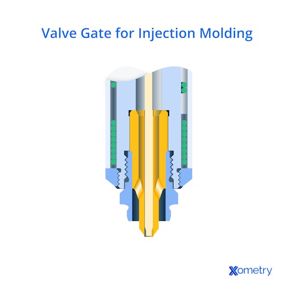
Valve gates are basically hot runner gates made with a unique gate pin or valve. Their job is to handle how the plastic lands in the mold and control the timing and location of the plastic entering the mold—something that minimizes weld lines and improves the part’s overall look. The gate works with the help of a pneumatic or pressure hydraulic valve, which controls the flow of melted plastic by shutting it off at just the right time to prevent two flows from meeting—particularly helpful for complex molds with multiple cavities.
You may find that you prefer these valves over traditional ones because they give you extra control over the filling process—which cuts down on issues like overflow and inconsistent fills. Plus, using these not only equals more control, but better quality too. Different factors, like the type, placement, and amount of gates used, can affect the cycle time, the appearance, and the durability of the final product. That’s why it’s so important to make sure you have the right gates for both the mold design and the overall process. With the wrong style of gate, you can easily run into major processing issues. To prevent any weld lines and flow markings, you’ll need to be highly methodical about the number of gates you use and where they go.
Valve gates are preferred over other gate types that tend to be difficult to adjust. Hot runner systems are true stars in the injection molding process because if they’re not around, plastic will keep flowing and wreak havoc on your manufacturing process.
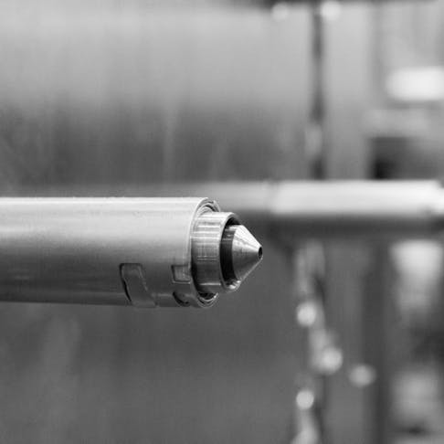
The gate nozzle uses a valve stem to completely seal it; this slides forward and closes the hole with mechanical force. While the mold is open and the part is ejected, the valve stem stays closed, so there’s no dripping or stringing. Thermal gated systems usually need melt decompression, but with a valve gate nozzle, this isn’t something you’ll need to worry about since the seal is strong and the hot runner manifold has enough pressure.

Benefits of Injection Molding Valve Gates
Valve gates can make a more aesthetically pleasing product. They can lower cycle times and completely do away with a runner removal operation. They also decrease the waste that comes from runners or sprues that get discarded. There’s not much discoloration or distortion since the part comes away from the gate without disrupting the plastic. Automated manufacturing benefits a lot from valve gating since it gives users faster mold start-ups and a wider processing timeline. It also keeps the melted plastic from stringing or dripping from the gate.
To elaborate, if the molds don’t need a properly frozen gate the cycle time is shorter. A valve gate nozzle cuts hold time, and as soon as the gate is closed, the melt can start to harden. With molds that are thermally gated, it’s necessary to have a frozen gate before the hold pressure gets released and screw recovery starts. Cooling time is cut as well because of the lower shear rate in the gate area.
High pressures and fill rates, as well as rapid cooling, are all hallmarks of thin wall molding—fast cooling lets the valve stem seal quickly after the cavity fills. If the cavity isn’t filled in half a second or less, the material will start to harden and make a frozen layer that can make further filling quite the challenge. This is where valve gates come in to save the day! They have an opening that allows for quick filling without ruining the flow, which keeps pressure drops to a minimum and helps cool the shear heating that pops up.
The nozzle tip’s setup will depend on the resin being used. When working with an amorphous resin, you’ll have to isolate the gate region thermally from both the nozzle and its tip. That’s not to say that semi-crystalline resins don’t need specific processing considerations to prevent premature solidification and ensure consistent part quality; they do. This involves more than isolating the gate region thermally, though; it often requires temperature control throughout the hot runner system to maintain melt flow.
When heat is transferred from the nozzle to the gate area, it can stall hardening and lead to deformation. For the resin to stay in liquid form, heat has to shift to the gate seal-off area using a nozzle that has been specifically designed for high-temperature, semi-crystalline, or unstructured resins, with a tip that has a built-in sealing surface that stretches to the molding surface, too.
FREE Injection Molding Design Guide
How it Works
The first step in the process is making sure you have the right-sized gate that matches the rest of the system so that the plastic can flow smoothly (the size and type will depend on the final part’s size and shape and the type of plastic being used). Before starting, the valve should be stable and controlled so that it doesn’t mess up the flow. The timing of the opening and closing should match the injection cycle, and this can be done with electrical controls. As we already covered, the gate stays open just long enough for the right amount of molten material to get into and fill the mold. Once full, the gate closes again to stop any extra plastic from entering and starts prepping for the next cycle while the part cools and hardens.
But how do you know if you’ve got the right amount of plastic in the mold? Well, there are a few ways to do this. The simplest is to track the time and just make a note of how long the plastic flows into the mold, but it’s not very reliable or precise because the flow can always change. Another method is using more than one gate (multi-gate injection) to fill the mold from different areas so that the plastic spreads evenly. Again, this isn’t perfect, but it’s better than manually counting the seconds. By far, the most accurate way (which is slowly becoming the norm in manufacturing) is with pressure sensors inside the mold that measure the pressure inside and let you know if it’s filled correctly. There are other methods, too, like flow and thermal monitoring, which are often used to improve quality control in the process.

Sequential Valve Gate Controllers
Sequential valve gate (SVG) controllers are often used to minimize stresses in the part and give it better mechanical properties. These systems open groups of gates, which allows for slow and controlled filling. With this level of control, you get less turbulence and even filling, which is particularly helpful when you’re making complex shapes or large parts. It’s typical to put multiple distinct gates in the valve gate system. In a case like this, these gates can be handled in two different ways.
The first way has all the gates being controlled together. Basically, all the gates get opened and closed at the same time, so there’s only one controller needed for all the valve gates. In the second method, you use SVGs that can open independently, so you need a separate controller for every gate or group of gates. So, for a tool with eight valves coupled into four groups, there would have to be four independent controllers that open two gates at a time. The controllers for both systems are the same, but for one, you just need more of them.
An SVG is a standard way to fill a mold in a quick and efficient manner, and it prevents gas bubbles, too. It also gives better flexibility as well as a shorter cycle, improved costs, and higher production. The system gradually fills the mold’s valves from the center and evenly distributes the material in the cavity, essentially improving the efficiency of the process without reducing the quality of the product.
FAQs on Valve Gates for Injection Molding
Below, our experts answer some of your most frequently asked questions about the topic of injection molding valve gates.
How does a hot runner system differ from a cold runner system?
The main difference between hot and cold runner systems is how much the plastic is heated on its way to the mold. The plastic moves through shafts called either sprues or runners to reach the mold. With cold runner systems, which are the most common, the gates attach to a cold runner and a hot sprue. The other option is a hot runner system (which is also known as a hot manifold system) where the plastic is heated consistently through the whole process. Valve gates are a standard example of a hot runner system.
The temperatures for both the molds and the runners are kept at the same point in cold runner systems. In this type of system, there are two plate options for the mold. A two-plate approach means the mold has two halves. It’s an easier way, but it means using an injection mechanism to get the part out of the mold. The three-plate format has the runner working on a separate plate, which lets users remove the piece from the mold without extra help.
A hot runner only has two plates that get heated with a manifold system. Hot runners work both inside and outside and with the help of rods, coils, and pipes. Molds that are heated internally work better when you want better control over the flow, whereas externally heated versions are great for materials that can’t handle high temperatures.
How do I choose a valve gate?
When you’re weighing options for gate types and locations for your system, there are some important details to keep in mind. These details can include the placement of the gate, as well as the mold’s design. The options for gates are limited to the location of the action and show surface, as well as how the part aligns in the mold. Think about the materials you want to use, too, and exactly what function you need it to serve.
Where should the valve gates be placed?
There are some criteria to follow when it comes to gate location. First of all, you need to keep the gates on the non-functional areas of the parts. You also need to attach them to the part’s thickest cross-section, which helps prevent sinking and possible voids. Lastly, gates need to go where they’re also easy to remove.
Are there any disadvantages to valve gates for injection molding?
The main factors that could cause some concern when it comes to these gates are that mold gate nozzles can sometimes leave witness marks, and the valve stem can cause a small indentation in the gate’s center if it overhangs through the gate. Also, while the quality of the gate is reliable and solid through various conditions, if the stem is opened for an extended amount of time, the resin can dry and harden inside the gate. This hardened plastic can keep the valve stem from properly closing in the gate hole, which can result in a post. Other drawbacks include the high cost and maintenance requirements—valve gates are more complex than simple cold runner gates, so need precise control, which can add to both upfront and operational costs.
How Xometry Can Help
Interested in injection molding? Xometry can help! Get started today by uploading your designs to the Xometry Instant Quoting Engine®. If you’re interested in using valve gates for your mold, you can add this to the notes section of your quotes or speak with one of our experts.
Disclaimer
The content appearing on this webpage is for informational purposes only. Xometry makes no representation or warranty of any kind, be it expressed or implied, as to the accuracy, completeness, or validity of the information. Any performance parameters, geometric tolerances, specific design features, quality and types of materials, or processes should not be inferred to represent what will be delivered by third-party suppliers or manufacturers through Xometry’s network. Buyers seeking quotes for parts are responsible for defining the specific requirements for those parts. Please refer to our terms and conditions for more information.


