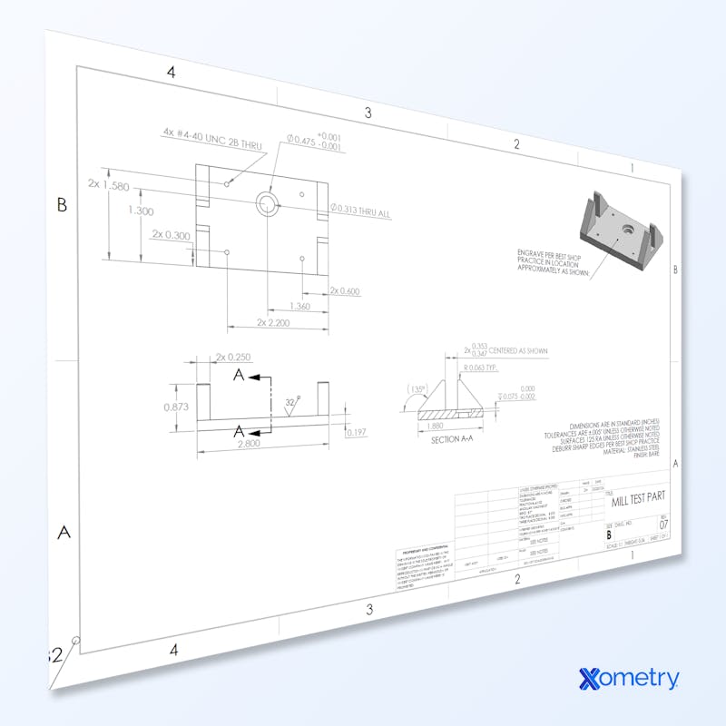
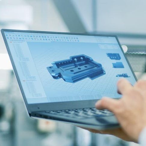
The design process for CNC machining requires precision and accuracy to produce quality designs. This is why there are recommended general design rules that apply to the most common features of CNC machined parts.
Tip #1: Avoid Excessively Thin Walls
Decreasing the wall thickness affects the stiffness of the material and reduces achievable accuracy as a result of inevitable vibrations during machining. The standard minimum thickness of walls is 0.794 millimeters for metals and 1.5 millimeters for plastics. If you require thinner walls, you can use other suitable and cost-effective manufacturing processes like sheet metal fabrication.
Tip #2 Avoid Features That Cannot be CNC Machined
An example of a feature that CNC mills, lace, or drills cannot produce is curved holes. If you require this feature or others that can’t be machined for your design, you can use electrical discharge machining or EDM machining instead.
Tip #3: Avoid Excessive Use of Tolerances
If you don’t specify tolerances in your design, the machine would simply use its standard tolerance. This helps save time and money. You should only specify tight tolerances when absolutely necessary. If you do specify tight tolerances, you should maintain consistency throughout your design. This helps reduce machining time.

Tip #4: Avoid Unnecessary Aesthetic Features.
Some aesthetic features cannot be efficiently machined. As a designer, you should ask yourself, “What CNC machining process with this feature require?” or “Should I use a five-axis or three-axis machining process?” You can improve your design by focusing on the accuracy required features rather than the settings it is best to use POST machining processes to change settings.
Tip #5: Design Cavities With Accurate Depth-to-Width Ratios
Cavities that are too deep can result in tall hanging, tall deflection, chip evacuation issues, and tool fracture. Cavity depth should not exceed three to five times their width. If larger depths are required, you should consider designing your part with a variable cavity depth.
Tip #6: Add a Radius When Designing Internal Vertical Edges
Most cutting tools are cylindrical and cannot machine sharp internal edges, meaning it is important to add a radius to internal edges in the design to avoid unnecessary wear and tear on the tool. A good rule of thumb is to add a radius of 130% of the milling radius. If you need sharp internal corners, consider adding undercuts instead of reducing the edge radius.
Tip #7: Limit Thread Length
Unnecessarily long threads increase machining costs. The strength of the connection does not increase any. When the thread length exceeds the size of the diameter by more than 1.5 times, designing thread should be no longer than two times the hole diameter. For blind holes, add an unthreaded length of at least half the diameter at the bottom of the hole.
Tip #9: Design Holes With Standard Sizes
Holes are machined quickly and accurately when standard drill bits are used. This means you won’t need end mills or reamers to finish the hole size to a nonstandard dimension. You should also limit the depth of holes to four times the diameter it is possible to machine deeper holes up to 10 times the diameter, but this will increase costs.
Tip #10: Avoid Unnecessary Text and Lettering
Any required text can be painted or laser engraved on the surface of the machine during the finishing process. If machined text is required, adhere to the following rules:
- Choose engraving instead of embossing. This way, less material is removed.
- Use 20 Point san serif fonts to help keep costs low.
If you would like to learn more design tips that will help you optimize your CNC machined parts, reduce machining times, and optimize your designs, we highly recommend downloading our free CNC Machining Design Guide. And, if you are ready to build your next big idea, you can upload your designs to the Xometry Instant Quoting Engine® and get instant pricing, lead times, and DFM feedback for your next CNC machined part.
Disclaimer
The content appearing on this webpage is for informational purposes only. Xometry makes no representation or warranty of any kind, be it expressed or implied, as to the accuracy, completeness, or validity of the information. Any performance parameters, geometric tolerances, specific design features, quality and types of materials, or processes should not be inferred to represent what will be delivered by third-party suppliers or manufacturers through Xometry’s network. Buyers seeking quotes for parts are responsible for defining the specific requirements for those parts. Please refer to our terms and conditions for more information.


