CNC (Computer Numerical Control) lathes are part of the logical progression of precision machining equipment. Like all lathes, they share historical roots with potters’ wheels and primitive woodworking lathes.
All motion axes of a CNC lathe are motorized, including its multi-tool post (capstan). The functions are automated, directed by a program that reads G-code, allowing the operator to remain hands-off and making the production entirely repeatable. CNC lathes have a series of distinct elements that identify them for what they are.
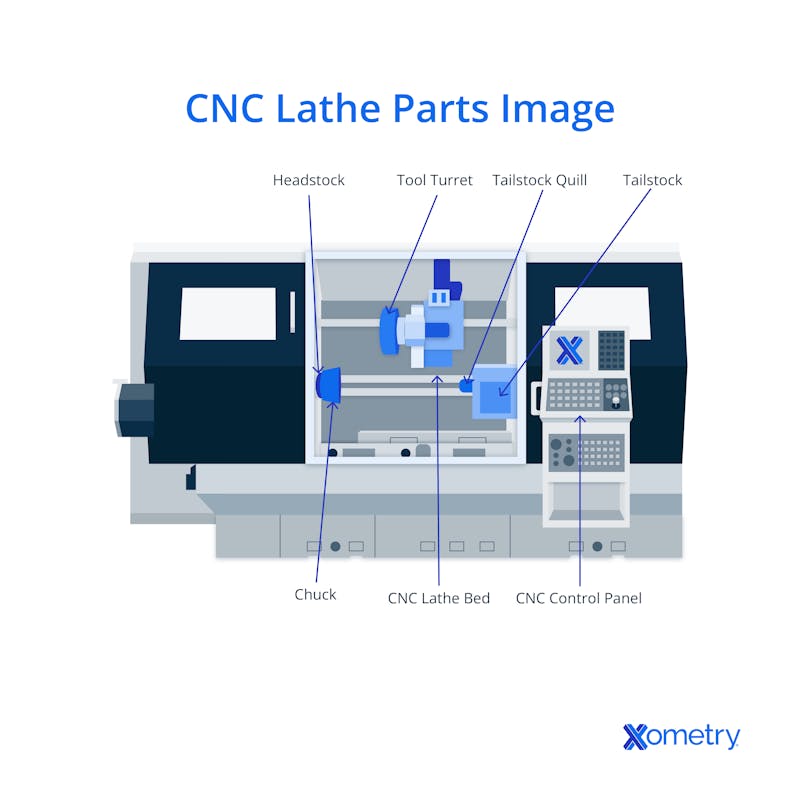
This article will focus on defining CNC lathes, identifying the lathe machine’s parts, examining how each element works, and advising about optimal use. Here is an image of how a CNC lathe looks with major parts labeled:

1. Headstock
The lathe headstock is the power behind the machine. As one of the most identifiable components of a CNC lathe, the headstock holds the workpiece and keeps it centered on the machine’s axis. The dimensions of the headstock will dictate the lathe’s “swing.” Swing is the maximum diameter of any (pre-machined) workpiece which can fit in the lathe. Though most tasks will not be so large, a machine with a big swing is sometimes very useful.
The other limiting factor for work capacity is the power of the motor. The motor drives the spindle, carries the chuck, and rotates the workpiece. The headstock’s main bearings carry significant and disruptive loads. Forces applied by the cutting tool may come from multiple directions. They can cause severe vibrations and potentially surpass the motor’s stall limit. This force makes the headstock’s main bearings an important service item that should be monitored, especially in heavily used machines.
2. CNC Lathe Bed
The bed of a lathe is the chassis that holds everything together. It is generally a beam that runs the length of the machine and supports all of the functional subassemblies. The bed must be stiff enough that it does not experience measurable distortion, even under the most extreme usage conditions.
The best beds can naturally damp out vibrations. Those with high hysteresis effects, for example, can dissipate vibrational energy as heat. A basic test for hysteresis properties is to simply hit the material with a hammer — a dull “thud” indicates high hysteresis while a higher-pitched “ding” is undesirable. CNC lathe beds are often made of: cast iron, mild steel, ductile cast iron, or a form of Granitan (an artificial casting stone substitute). Materials such as Granitan carry minimal risk of cracking and chipping, improved toughness, and significant vibration damping.
3. Chuck
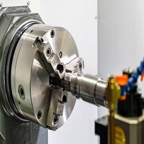
The chuck is perhaps the most critical component of a lathe. It clamps the workpiece at the center of rotation and allows easy loading and unloading. The chuck is attached to — but is not part of — the headstock. Various chuck types are employed in CNC lathes, including:
- Three-Jaw (Universal) Chucks: The jaws of a universal chuck are generally stepped on one end to accommodate different sizes of workpieces. The other end is beveled to precisely grip smaller diameters.
- Four-Jaw Chucks: These are similarly constructed and operate in a similar way to three-jaw universals. The difference is that their four clamping jaws are driven by four independent screws that make centering the workpiece a delicate positioning exercise but allow the clamping of square pieces and less regular objects.
- Combination Chucks: This type of chuck is more costly but reduces the variety of tools the machinist must keep on hand. Operationally, they are more difficult to use, as the jaws must be adjusted manually to their mutually centered position.
- Magnetic Chucks: This type of chuck is most useful when turning materials that aren’t strong enough to withstand the clamping forces of a jaw chuck. Only ferrous workpieces are compatible with magnetic chucks.
- Collet Chucks: These use three or more jaw sections sized to be a close fit to only cylindrical workpieces. Collet chucks are precise and effective, but each one is limited to a narrow range of diameters. Collets are most often used to hold tools.
- Drill And Pin Chucks: These are generally used as sub-chucks, held in a collet or universal chuck. Drill and pin chucks allow clamping of small workpieces (or tools) that are too small for ordinary chucks.
4. Tailstock
The tailstock of a lathe is critical in several tasks. It stands opposite the headstock on the same axis of rotation and can firmly lock onto the workpiece’s far end. The extra support can be important to resist significant operating loads. Alternatively, a drill bit may be mounted to the tailstock to drill into the workpiece’s rotational axis. Tailstocks generally consist of a Morse taper tool stem holder that sits in a precision feed and allows large force for longitudinal position control. Tailstock functions include:
- Holding a centering tool to provide lateral force support. It prevents long workpieces from bending away from the cutter.
- Holding a drill chuck for small-diameter twist drills. This drill chuck is fed into the outer workpiece end, precisely in the center - and then drilled into the work at a precise depth.
- Holding a larger drill bit with a Morse taper shank so it can drill directly into the workpiece’s end.
5. Tailstock Quill
The quill portion of the tailstock is what grips the Morse taper. It is an externally cylindrical mount that allows chucks, drills, etc to be fitted to the tailstock. The quill is the movable part that can be driven towards the workpiece for drilling or center-stabilization purposes.
6. Foot Switch or Foot Pedals
Foot switches or foot pedals allow the operator to directly control machine setup or unload functions while their hands are busy in the machine. These pedals can control several functions such as: opening/closing of the chuck (if it is hydraulically or pneumatically operated), positioning of the tailstock (for centering and support setup), and acting as an emergency stop to avoid programming errors and/or accidents.
7. CNC Control Panel
The operator controls on a CNC lathe typically consist of two parts: the machine panel and the control panel. The machine panel allows the operator to adjust the tool's operational characteristics and cutter position. It is used to manually jog (make small alterations to the position of) the machine's driven axes. The control panel, on the other hand, can be used to enter programs into memory and to edit or alter programs already in memory. This part of the operation is displayed on the integrated screen and shows the G-code being entered or modified.
8. Tool Turret
The tool turret is the business end of the CNC lathe. Various tools are placed into an operational position and their cutting faces are precisely logged in the machine setup. Each tool in the turret can be rotated one at a time into the cutting position. This feature differs from manual (turret or capstan) lathes in that the tool selection and positioning are performed automatically.
What Is a CNC Lathe Machine?
A CNC lathe is a fully automated machine capable of precise turning and drilling operations. It follows G-code programming intended for subtractive manufacture (cutting) and starts with either a suitable material blank or a preform. Automated (CNC) lathes allow operators to focus on other tasks while the machine works, so they improve productivity while simultaneously making more precise parts than manual machines. For more information, see our guide on CNC Machining.
How a CNC Lathe Machine Works
A CNC lathe machine works by reading G-code, a translated version of CAD design code. The G-code file automates the manufacture of complex parts, making high-precision items in a repeatable manner with short processing times (once set up). The first part must be manually checked for accuracy against a drawing before multiple parts are made. In most cases, the headstock motor is a synchronous single- or 3-phase device that uses a variable frequency drive. The other axes will generally be driven by stepper motors to allow open-loop control. A CNC lathe is an adaptable machine type that can undertake precise and repetitive tasks, following its programming. Two parts made from the same code should be essentially indistinguishable.
How To Determine the Parts of CNC Lathe Machine
To determine the parts of a CNC lathe machine, it is recommended to study the user manual and breakdown images of your machine. You should have a clear understanding of each component before progressing to cutting metal. The descriptions of machine elements (headstock, chuck, lathe bed, etc.) are generic. Nomenclature and layout may vary between manufacturers. The lathe machine diagram for your tool will give you the manufacturer's version of the naming.
Best Upgrade for CNC Lathe Machine Parts
The best upgrade for CNC lathe machine parts varies depending on user needs. A range of possible improvements can be considered depending on the quality of the lathe machine parts. Examples are:
- Improved Controller: Better controller hardware can improve capabilities and program editing. Non-specialist hardware from sources like Amazon and AliExpress can help, as can the manufacturer of your machine.
- Improved Tooling: High-quality drills, cutters, reamers, and borers have significant effects on part quality and throughput. In general, carbide-tipped tools give better results, but they must be handled with the right level of care. Specialist suppliers like cuttershop.com offer competitive prices.
- Hydraulic or Pneumatic Chucks: These are available for most machine formats and can reduce the time it takes to load and unload the machine. Non-specialist suppliers like Amazon and AliExpress are good sources for aftermarket chucks. Read reviews and make sure you know what you’re buying. At the higher end, suppliers like Valder come highly recommended.
- Improved Coolant Supply: Coolant is critical to high-quality metal cutting operations and is even important for some plastics. Many entry-level machines have limited automated coolant application capability (or none at all). Flood coolant systems from suppliers like Grainger and others are very effective.
- Full Enclosure: A silencer hood can improve the environment around the machine. It reduces coolant splash and protects workers from injury.
How Xometry Can Help
Xometry provides a wide range of manufacturing capabilities including CNC machining, 3D printing, injection molding, laser cutting, and sheet metal fabrication. Get your instant quote today.
Disclaimer
The content appearing on this webpage is for informational purposes only. Xometry makes no representation or warranty of any kind, be it expressed or implied, as to the accuracy, completeness, or validity of the information. Any performance parameters, geometric tolerances, specific design features, quality and types of materials, or processes should not be inferred to represent what will be delivered by third-party suppliers or manufacturers through Xometry’s network. Buyers seeking quotes for parts are responsible for defining the specific requirements for those parts. Please refer to our terms and conditions for more information.


