Both countersink and counterbore holes are features we often see in our customers' CNC machined part designs. The most obvious difference between the two is probably their shape, but aside from that, there are a few others worth knowing about. Let’s look at these hole types in more detail and find out when they’re best used.
What is a Countersink Hole?
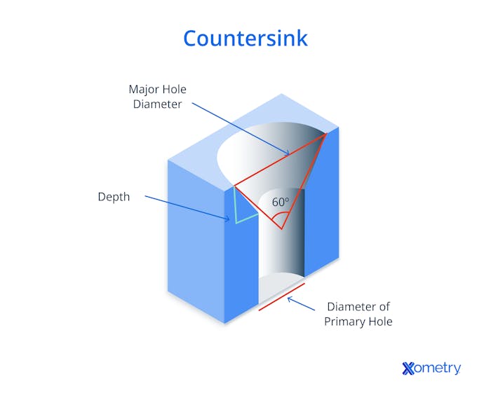
Often used in woodworking on softer materials, countersink holes (callout symbol “⌵”) are cylindrical holes made to match the angle of a screw so it can be secured in place and sit nice and flush. It comes in many angles, from 60° to 120°, although 90° is the most common. Here’s an example of a countersunk hole:

The cone-shaped hole’s widest part (the “Major Hole Diameter” shown in the image above) is specifically designed for a screw or bolt to be inserted. The angle is important when it comes to these holes because this is what will determine how deep the fastener can be sunk in—the deeper it goes, the more secure it will be. Aside from making a joint stronger, a countersunk hole allows the fastener to go in at a shallower angle, lowering the chances of it stripping the material.
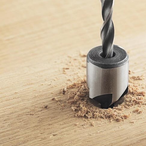
These holes can be made with a drill and a countersink bit or machined with endmills. The most important thing to do is make sure the hole is the right size and shape for whatever is going into it.
What is a Counterbore Hole?
Counterbore holes (callout symbol “⌴”) are also cylindrical and designed to increase a hole’s opening and make a flat bottom, which helps fasteners sit flush with (and below, if necessary) the surface of the piece of material you’re working on. Although this is pretty much their only purpose, they are useful for fasteners like socket-head screws to sit flush. Their walls are 90° perpendicular from the material’s surface, and they lack any taper, resulting in a straight hole with a flat bottom.
Making one of these holes is a breeze: first drill a small pilot hole with a drill bit of an appropriate diameter, and then make that hole bigger with an endmill or a counterbore cutter which is specially designed for the job. If you make a counterbore hole big enough for a washer, this could ramp up its holding power.
Countersink vs. Counterbore: Size
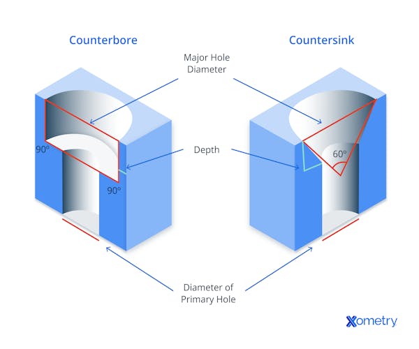
Counterbore holes are normally not as deep as a countersink hole, and instead of having tapered sides, they’re straight. They also tend to have more holding strength than countersink holes for two main reasons: the force applied by the socket cap screw head is parallel to the axis, and the force applied by the screw or bolt is evenly distributed over a larger surface area. You won’t find these strengths with countersunk holes, which have tapered angled sides and unevenly distributed force. The below image will give you a better idea of their differences.
Countersink vs. Counterbore: Shape
A countersink is a cone-shaped hole. A counterbore, on the other hand, is a cylindrical flat-bottomed hole that is created to contain a socket or hexhead cap screw. In other words, a countersink hole is cone-shaped while a counterbore hole is cylindrical.

Countersink vs. Counterbore: Drilling Angle
Depending on the application, drill bits that come in different sizes and drilling angles are available for producing countersinks. Some of the applied angles include 120° angles, 110° angles, 100° angles, 90° angles, 82° angles, and 60° angles. However, the most commonly applied drilling angles are 82° angles and 90° angles. For the best result, the angle of the countersink must be matched with the tapered angle on the underside of the fastener head. On the other hand, a counterbore hole has the sides parallel to each other and therefore does not require any tapering.
Countersink vs. Counterbore: Callout Symbol
The callout symbol for a countersink hole is "⌵" while the callout symbol for a counterbore hole is "⌴". The symbols attempt to depict the cross-sectional shapes of the different hole types after the countersink or counterbore has been created.
Countersink vs. Counterbore: Applications
Countersunk holes are used for wood and metal screws, while counterbores are mainly used for larger fasteners, like lag bolts. Generally, countersinks need smaller pilots than counterbores, which is why the latter is used for heavy-duty tasks in construction, machinery, and automotive.
Countersink sizes are typically expressed in terms of their diameter (the width of the hole), depth (the distance from the material’s surface down to the pilot hole’s top), and the angle of the countersink. Counterbore sizes typically range from 3/16” to 1”, and countersinks 1/16” to ½”. We always recommend that our customers check a standard counterbore and countersink size chart to make sure their parts are designed to work with standard tooling.
Countersinks can easily be applied to sheet cut or sheet metal products where counterbores can be cost prohibitive due to a machining operation.Greg PaulsenDirector, Applications Engineering
| Hole Type | Description |
|---|---|
Hole Type Blind hole | Description A type of counterbore hole that doesn’t go all the way through the other side of a workpiece. Can be made by drilling, reaming, or milling. |
Hole Type Simple hole | Description A machining hole that passes all the way through to the other side of a material. It has a single diameter and is great for fastening parts together. |
Hole Type Counterdrill hole | Description This type has a countersink recessed below the surface. |
Hole Type Tapped hole | Description Created through a tapping process that cuts threads into the hole’s walls, this hole is handy if you need an alternative to nuts and bolts. |
Hole Type Spotface | Description This is basically a shallow counterbore hole with a smooth and high surface finish. |
Other Types of Holes in Machining
How Xometry Can Help
Xometry can help with all your machining needs, with services like CNC drilling, jig boring, and so much more. We have a plethora of manufacturing capabilities, including CNC machining, 3D printing, injection molding, laser cutting, and sheet metal fabrication. You can get started by uploading your CAD files to the Xometry Instant Quoting Engine® and get an instant quote today!
Disclaimer
The content appearing on this webpage is for informational purposes only. Xometry makes no representation or warranty of any kind, be it expressed or implied, as to the accuracy, completeness, or validity of the information. Any performance parameters, geometric tolerances, specific design features, quality and types of materials, or processes should not be inferred to represent what will be delivered by third-party suppliers or manufacturers through Xometry’s network. Buyers seeking quotes for parts are responsible for defining the specific requirements for those parts. Please refer to our terms and conditions for more information.


