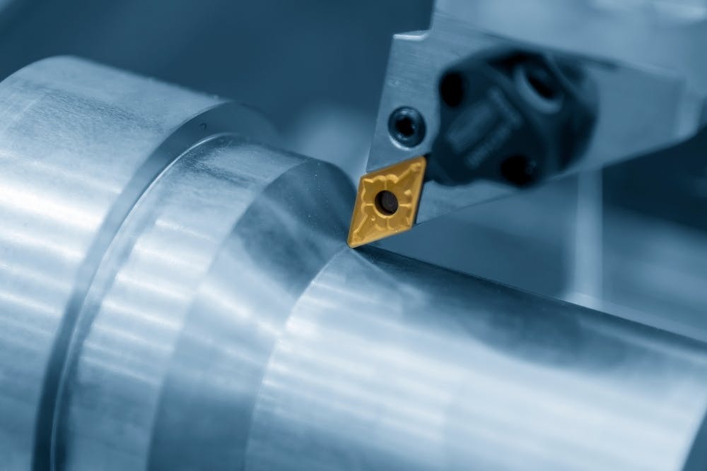
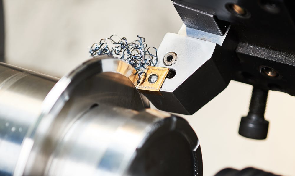
Step turning is one of the fundamental turning operations and is used to great effect in several industries. It is used to produce shafts with varying diameters, with the change between diameters being a perpendicular step. Step turning is used primarily in machine design applications for shafts that need to have bearings, drive elements, and power transmission components installed on them. These components typically all require different diameters. Step turning can produce precise geometries but can also be wasteful, especially if there is a large difference between the various stepped diameters.
This article will discuss what step turning is, how it works, and its purpose, advantages, and disadvantages.
What Is the Step Turning on Lathe Machine?
Step turning refers to the process of machining a cylindrical shaft with at least two different diameters. The smaller diameters are produced by removing material using a straight cutting or parting tool so that there is a step change where the diameter changes.
Is Step Turning the Same as Taper Turning?
No. While both step turning and taper turning are done on a lathe, taper turning results in a gradual reduction in diameter along the axis of the shaft to produce a part whose cross-sectional profile is tapered like a cone. An example of a tapered shaft would be a milling machine tool holder where the tapered section creates a snug fit that also aids in locating the tool cylindrically in the spindle. Figure 1 below shows both a step cut and a taper cut:

Taper turning.
Image Credit: Shutterstock.com/Pixel B
What Is the Purpose of Step Turning?
The main purpose of step turning is to create a shaft with multiple different diameters to fit up with the requirements of such components as bearings, gears, or pulleys. The change between the diameters must be a step that is perpendicular to the shaft axis to allow for the accurate location of mating parts.
Where Is Step Turning Commonly Used?
Step turning is commonly used in machine design applications. For example, a shaft that is driven by a gear motor may need multiple diameters to allow the fitment of bearings as well as pulleys, gears, or chain sprockets, depending on the application.
How Does Step Turning Differ From Other Types of Turning?
Step turning is different from other turning operations in the sense that it produces a shaft with step diameter changes along the length of the shaft. This is different from straight turning, during which a shaft is turned down to a single diameter, or taper turning which creates a shaft with a gradually changing diameter. It must, however, be noted that it is possible for step turning to simply be one of many turning operations on a shaft.
To learn more, see our article on Types of Turning.
Is Turning the Same as Milling?
No, turning and milling are two distinct processes. Turning refers to the process of shaping a cylindrical part on a lathe by spinning the workpiece while introducing a non-spinning tool into the side of the part to cut the desired cylindrical shape. Milling, on the other hand, is a process that shapes a part by placing a workpiece into a fixture on the bed of a milling machine and then introducing a spinning tool into the material to shape the part. A milling machine can produce non-cylindrical components.
How Does a Step Turning Process Work?
The process of step turning begins with fixing a cylindrical piece of material, either a round bar or a hollow bar, into the chuck of the lathe. Next, the cutting tool is selected and mounted to the tool post. In general, a straight cutting tool can be used. The required rotating speed of the lathe is selected based on standard speed and feed recommendations, and the machine is started up.
The end of the workpiece must then be faced using a straight-cutting tool. Next, the outer diameter of the workpiece is cut using a standard, straight cutting tool. This process removes any mill scale while also discarding any deviations in the diameter of the part. This first cut can typically be a rough cut that is meant to remove a lot of material in one pass. Then a final finishing pass can be performed to reduce the diameter to match the diameter of the largest required diameter on the workpiece.
Starting at the end furthest away from the chuck, the cutting tool is then introduced into the rotating workpiece. Depending on the depth of the step, either a single cut or multiple cuts are performed to reduce the diameter. If the step requires a slight radius, which is typically the norm to reduce stress concentrations, then the straight-cutting tool can be moved axially along the shaft performing multiple cutting passes until the shaft matches the required diameter and reaches the corner of the step. Then, the tool can be backed out perpendicularly to the shaft axis to produce a straight perpendicular edge. The tool radius determines the corner step radius; for larger radii, a CNC machine would need to be used to create the radius.
What Are the Materials Suitable for Step Turning?
Most metals and plastics are suitable for step turning. In general, step turning is performed on materials that are used for making shafts, such as stainless steel or low to medium-carbon steels. If a material can be cut on a lathe, then it can be used for step turning.
What Are the Necessary Tools for Step Turning Process?
Step turning is a fundamental turning operation and can be performed on even the most rudimentary lathes. To successfully perform this operation, certain tools are required, as described below:
1. Vernier Caliper
The vernier caliper is used to measure the diameter of the shaft throughout the turning process. Digital vernier calipers can be used to speed up the process. After each turning pass, the diameter must be measured to determine how much material must still be removed to achieve the final diameter. Verniers are typically accurate to the second decimal place. For more precise measurements, a digital micrometer can be used, which can be accurate to the third decimal place. It must be noted that if step turning is performed on a CNC lathe, then vernier calipers are not required, apart from using them for a standard quality control check at the end of the process.
2. Parting Tool
A parting tool has a rectangular shape with sharp corners. It is designed to cut perpendicularly into the shaft and is often used to separate the finished component from the stock material. It is a tool that can essentially perform a facing and a cutting operation in one. A parting tool can be used in step cutting by advancing the tool into the material until it has created a groove with the diameter of the step. Then, the turning tool can be used to remove the remaining material up to the groove. This is ideal if a sharp corner is required for assembly purposes.
3. Turning Tool
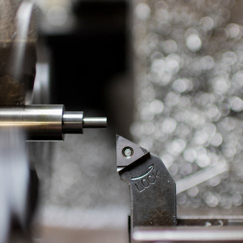
A turning tool is the most common lathe tool and can take on many different shapes. A common example is shown in Figure 2 below:

Turning tool.
Image Credit: Shutterstock.com/Dmitry Kalinovsky
This tool is used for the bulk of the material removal during turning operations, and can also be used to produce steps. These tools normally have a noticeable nose radius which results in a small radius at the root of the step.
How Long Does the Step Turning Process Take?
The speed of the step turning process depends on many factors. The material to be turned has a big impact on the possible feed and speed rates for a machining operation and thus affects machining time. Next, the difference in diameter between the steps and the number of steps will determine how many passes are needed to work the material down to the various specified diameters. Finally, high-precision diameters take longer to achieve, as multiple finishing passes may be required.
How Accurate Is Step Turning?
The accuracy of step turning depends on the machine and the operator. If performed by an experienced machinist, step turning can be accurate enough to achieve bearing-fit tolerances.
What Are the Advantages of Step Turning?
Step turning is a fundamental machining operation and can produce shafts with multiple diameters. Listed below are some common advantages of this technique:
- Speed: The shaft can be machined without having to remove it from the machine. This means the process is fast and well-suited to large-volume manufacturing when coupled with CNC machining.
- Complex Shafts: Step turning can produce shafts with multiple precise diameters that are well-suited for various machine design applications.
- Low Cost: Creating a single part is cheaper than making multiple smaller shafts, assembling, welding, and machining them.
What Are the Disadvantages of Step Turning?
One of the main disadvantages of step turning is the potential material wastage. For example, consider a shaft that requires 45 mm, 40 mm, and 25 mm steps. This means that a bar of 50 mm diameter stock workpiece will need to be used, and by the time the 25 mm diameter step is reached, half of the diameter of the blank is wasted. However, these issues can be mitigated with good design practices. For example, selecting shafts that are closer to standard stock sizes or choosing mechanical elements like bearings, gears, or taper locks that do not require significantly large step changes.
What Is the Difference Between Step Turning and Facing?
Facing is a turning operation that is performed on the end faces of a workpiece and is performed over the entire face of the part. On a shaft, this would be the face (or faces) perpendicular to the shaft axis. Step turning also produces faces that are perpendicular to the shaft axis, but they are not on the ends of the shaft and do not extend over the entire cross-sectional area of the shaft—only that part that forms the step to the next diameter.
Summary
This article presented step turning, explained it, and discussed its purpose and process. To learn more about step turning, contact a Xometry representative.
Xometry provides a wide range of manufacturing capabilities, including machining and other value-added services for all of your prototyping and production needs. Visit our website to learn more or to request a free, no-obligation quote.
Disclaimer
The content appearing on this webpage is for informational purposes only. Xometry makes no representation or warranty of any kind, be it expressed or implied, as to the accuracy, completeness, or validity of the information. Any performance parameters, geometric tolerances, specific design features, quality and types of materials, or processes should not be inferred to represent what will be delivered by third-party suppliers or manufacturers through Xometry’s network. Buyers seeking quotes for parts are responsible for defining the specific requirements for those parts. Please refer to our terms and conditions for more information.

