Countersunk holes are a type of engineering hole most commonly used for the aesthetic flush fitting of fasteners to render a product surface smoother. This article will discuss exactly what they are, their applications and uses, as well as how to drill one. We also provide all the relevant countersink hole size charts.
What is a Countersink Hole?
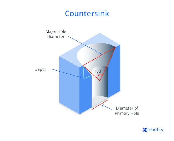
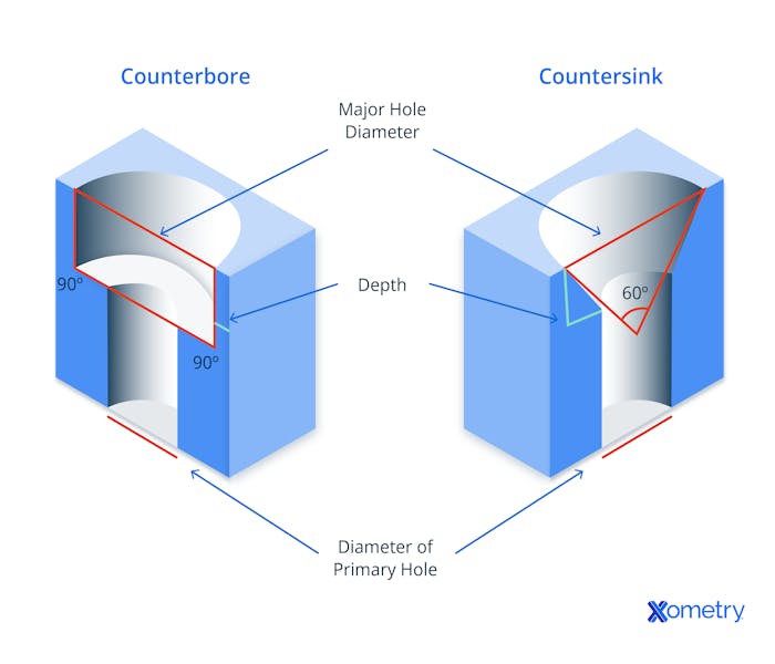
A countersink hole is one in which the outer edge of the hole has been opened up to a conical entry. For ANSI/Imperial fasteners, it is commonly at 82°, 90° for metric fasteners, 100° for BA threaded fasteners, and 120° for sheet metal rivets. The ISO callout for a countersink is: ⌵. The countersink is generally sized according to the head dimensions of the fastener being fitted, such that a flat-faced fastener will sit flush with the countersunk surface. It is common to further recess the head to sit below the countersunk surface by increasing the diameter of the countersink. This process allows for variations in the head and potential distortion of the drive recess in the fastener, caused by driver bruising.
Where the countersink is further drilled parallel, this is referred to as a “counterdrilled” hole. This allows plugs or caps to be fitted, which renders the fasteners invisible, taking the improved appearance to its logical conclusion. This generally applies to fasteners that are not at risk of requiring later removal. Additional practical reasons for countersinking holes to bury the heads of fasteners are: in moving equipment, to remove obstacles and reduce the need for clearances; in walkways, and on stairs and gantries, to remove obstructions and trip hazards; and to bury fastener heads where additional components must overlay the fastener, removing the need for precise relief holes/recesses in the overlying part.
How to Drill a Countersink Hole
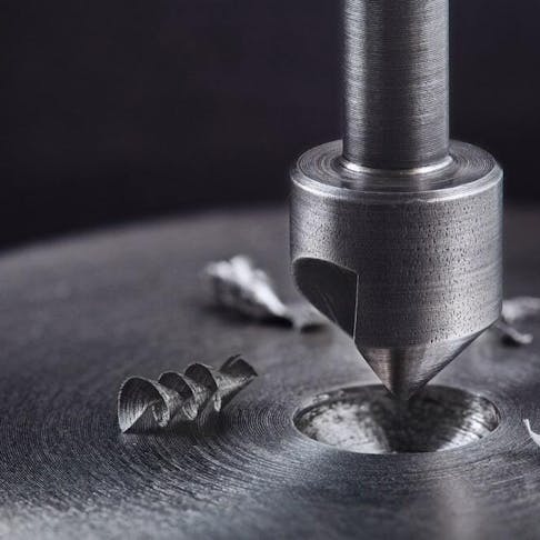
Countersinking is usually performed as a secondary operation after the hole is formed/drilled. The countersink tool does not cut at its center of rotation and can, in some cases, have a smooth post that locates the tool into the hole to ensure a smoother start and precise centering.
Countersinking tools are specialist drill bits and cutters that can have multiple cutting faces. In the case of larger countersinks, and particularly those for machine use, they commonly have only one flute/cutter. This feature aids in centering on the hole and producing a more even and regular cut.
Countersinking operations can be manual or machine performed but involve plunge cutting a specialist cutter of the correct included tip angle into a pre-made hole, to a defined and controlled depth, to produce a standardized and repeatable conical recess. A countersink hole is pictured below:

Choosing the Right Tap for a Countersink Hole
Where the countersunk hole is formed/drilled through to the other side of the part, the tap required for threading such a hole is a taper or middle type. These two forms of tap have the initial threads ground away, allowing the tap to enter the hole and correctly center from the start of tapping/thread cutting.
For a through hole, the selection of taper or middle taps depends on the depth of the hole to be tapped. There must be enough total length of unaltered tap and shank combined to allow the tap to penetrate deeply enough to complete the thread through the part.
Where the hole is blind, tapping requires a two-stage operation. The thread is initiated with a taper or middle tap and then completed with a bottoming tap to the required depth. The choice between taper and middle taps is driven by the blind hole depth. Where its use is possible, the taper tap gives a softer and more certain start to the thread cutting. But if the taper prevents effective cutting as it is longer than the blind hole is deep, it is necessary to use a middle tap.
Countersink Hole Size Charts
The tables below list the typical countersink dimensions for socket flat head screws to sit flush with the surface they are sunk into.
| Fastener Size | Countersink Diameter | Countersink Angle (°) |
|---|---|---|
Fastener Size #0 | Countersink Diameter 5/32 | Countersink Angle (°) 82 |
Fastener Size #1 | Countersink Diameter 3/16 | Countersink Angle (°) 82 |
Fastener Size #2 | Countersink Diameter 7/32 | Countersink Angle (°) 82 |
Fastener Size #3 | Countersink Diameter 1/4 | Countersink Angle (°) 82 |
Fastener Size #4 | Countersink Diameter 9/32 | Countersink Angle (°) 82 |
Fastener Size #5 | Countersink Diameter 5/16 | Countersink Angle (°) 82 |
Fastener Size #6 | Countersink Diameter 11/32 | Countersink Angle (°) 82 |
Fastener Size #8 | Countersink Diameter 3/8 | Countersink Angle (°) 82 |
Fastener Size #10 | Countersink Diameter 7/16 | Countersink Angle (°) 82 |
Table Credit: https://engineersbible.com/
| Fastener Size | Countersink Diameter | Countersink Angle (°) |
|---|---|---|
Fastener Size 1/4 | Countersink Diameter 9/16 | Countersink Angle (°) 82 |
Fastener Size 5/16 | Countersink Diameter 11/16 | Countersink Angle (°) 82 |
Fastener Size 3/8 | Countersink Diameter 27/32 | Countersink Angle (°) 82 |
Fastener Size 7/16 | Countersink Diameter 29/32 | Countersink Angle (°) 82 |
Fastener Size 1/2 | Countersink Diameter 1 | Countersink Angle (°) 82 |
Fastener Size 5/8 | Countersink Diameter 1 1/4 | Countersink Angle (°) 82 |
Fastener Size 3/4 | Countersink Diameter 1 1/2 | Countersink Angle (°) 82 |
Fastener Size 7/8 | Countersink Diameter 1 3/4 | Countersink Angle (°) 82 |
Fastener Size 1 | Countersink Diameter 2 | Countersink Angle (°) 82 |
Fastener Size 1 1/8 | Countersink Diameter 2 1/4 | Countersink Angle (°) 82 |
Fastener Size 1 1/4 | Countersink Diameter 2 1/2 | Countersink Angle (°) 82 |
Fastener Size 1 3/8 | Countersink Diameter 2 3/4 | Countersink Angle (°) 82 |
Fastener Size 1 1/2 | Countersink Diameter 3 | Countersink Angle (°) 82 |
Table Credit: https://engineersbible.com/
| Thread | Countersink Diameter (mm) | Countersink Angle (°) |
|---|---|---|
Thread M3 | Countersink Diameter (mm) 6.94 | Countersink Angle (°) 90 |
Thread M3.5 | Countersink Diameter (mm) 8.96 | Countersink Angle (°) 90 |
Thread M4 | Countersink Diameter (mm) 9.18 | Countersink Angle (°) 90 |
Thread M5 | Countersink Diameter (mm) 11.47 | Countersink Angle (°) 90 |
Thread M6 | Countersink Diameter (mm) 13.71 | Countersink Angle (°) 90 |
Thread M8 | Countersink Diameter (mm) 18.25 | Countersink Angle (°) 90 |
Thread M10 | Countersink Diameter (mm) 22.73 | Countersink Angle (°) 90 |
Thread M12 | Countersink Diameter (mm) 27.21 | Countersink Angle (°) 90 |
Thread M16 | Countersink Diameter (mm) 33.99 | Countersink Angle (°) 90 |
Thread M20 | Countersink Diameter (mm) 40.71 | Countersink Angle (°) 90 |
Table Credit: https://engineersbible.com/

Countersinking requires a conical rather than cylindrical recess, angle, and diameter to match the underside of the intended fastener head and applies to:
- All types of heads for drives used for rotating threaded fasteners—internal hex, Phillips, crosshead, Torx, pin Torx, slot, and many more.
- All conical-bottomed threaded fastener head types such as pan, button, cap, and more.
- Wide variety of knock-down joint fasteners that are not threaded, such as quarter-turn locks and more.
- Various rivet types such as pop, peened, and push rivets
- A counterbore hole serves the purpose of recessing and thereby concealing fastener heads that have flat, perpendicular lower faces.
Counterbore holes have a cylindrical opening that’s larger in diameter than the hole, cut at the outer face of a blind or through hole, whose diameter and depth are defined to fit a particular fastener head, or a family of fastener heads, or according to ANSI and ISO standards.
Other Engineering Hole Types
While there are many conflicting and overlapping definitions of hole types listed among engineering handbooks, guides, websites, and discussion groups, the five most important and commonly employed hole types (other than countersunk) are:
- Through: A parallel-sided hole of any diameter cut through a part.
- Blind: A parallel-sided hole of any diameter cut into a part but not penetrating to the other side. Blind holes retain the end shape of the cutter that made them, such as a twist drill (118 or 135° included angle conical tip), the ball-ended mill (hemispherical tip), end mill (flat, square tip), Forstner bit (flat, perpendicular cutter face with a tapered center spike for location), or auger (flat, perpendicular cutter face with a tapered threaded center spike for location).
- Spotface: A blind or through hole that has had a perpendicular and flat-faced shallow shoulder cut at the material face. The purpose is to provide a high-quality surface on otherwise rough-surfaced parts or to provide a perpendicular landing surface on otherwise curved-surface parts.
- Tapped: A through or blind hole that has had part or all of its length cut such that thread results, expanding the effective diameter by cutting the thread features into the wall of the hole.
How Xometry Can Help
To learn more about countersink holes, feel free to contact a Xometry representative. We offer a whole range of manufacturing services, including CNC machining, for all prototyping/production requirements. To find out more, head on over to our website, or, you can alternatively upload your designs to the Xometry Instant Quoting Engine® and get a quick, free, and no-obligation quote today.
Disclaimer
The content appearing on this webpage is for informational purposes only. Xometry makes no representation or warranty of any kind, be it expressed or implied, as to the accuracy, completeness, or validity of the information. Any performance parameters, geometric tolerances, specific design features, quality and types of materials, or processes should not be inferred to represent what will be delivered by third-party suppliers or manufacturers through Xometry’s network. Buyers seeking quotes for parts are responsible for defining the specific requirements for those parts. Please refer to our terms and conditions for more information.


