CNC milling is a machining process that combines the traditional milling manufacturing method with a computer. Milling is a very important process here at Xometry and you can get an instant quote on milling any time you need one! Let’s learn more about this useful process.
What is CNC Milling?
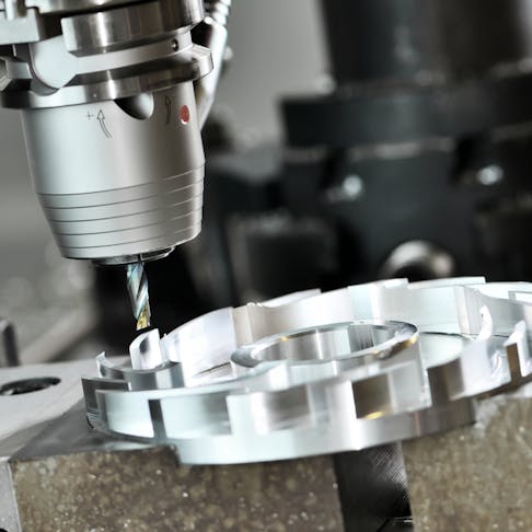
CNC milling is the same milling machining process that we know and love, with the addition of computer control. Milling is the cutting of a material like metal, plastic, or wood, using a rotating tool. Every aspect, like cutter toolpath, feed rate, and tool sequence, is dictated by the controls.
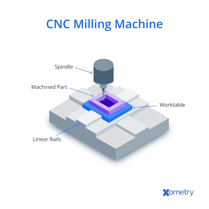
There are several different types of CNC milling machines that allow varying levels of complexity in the cutting process. The simplest machines tend to have three axes of motion, but more complex models can have five or more. These machines are used for making more complex parts. The picture below shows what a CNC milling machine looks like

A wide range of tools is available to support variations in the milling process, from standard end mills and drill bits to special face milling and profile milling tools. With so many different types of CNC mills and cutters, almost any shape or design can be produced on a CNC milling machine.
The first commercially available CNC milling machine was developed in 1952 by Richard Kegg, in collaboration with J.F. Reintjes and his team at the Massachusetts Institute of Technology. Since then, numerous advancements in CNC milling have been developed, including producing more complex CNC milling machines and automation.
It uses a set of cutting tools that rotate to create parts from blocks of material in one cycle. Material is removed from a workpiece when the cutting edge of the tool contacts the workpiece as it rotates. During a milling cut, a workpiece is held securely in place while the rotating cutter gets to work removing material. The exact tool paths, cut depth, XYZ and axis travel, and spindle RPM will all have been previously uploaded to the control program.
The process is used in many different industries — automotive, aerospace, agriculture, construction, electronics, and consumer products — to make all sorts of parts, like engine/landing gear components and fuel tank panels for aircraft, as well as medical devices such as scalpels and implants.
Steps in the CNC Milling Process
To get from the CAD model to the physical part (made by Xometry or elsewhere!), several tasks must be completed, and we list these below for you.
1. Make your CAD Model
First things first, you have to create a 3D CAD model for the part you want to make, and include all the important information, like the part’s size, geometry, and shape of the part. Perhaps more important is making sure that your CNC milling machine is actually capable of cutting your CAD model. Parts should be designed with no (or minimal) undercuts. The size of the undercut that can be machined depends on the capabilities of the specific CNC machine. Undercuts are deep-set or sunken features in a part, and these can’t be cut with standard tools. CNC mills can technically make these cuts, but you’ll more than likely need specialized tools and/or multi-axis milling machines. Make sure to factor these into your budget because both tooling and manufacturing expenses could rack up costs.
2. Converting CAD to CNC
When the 3D CAD model is ready, the next step is creating a CNC program to control and instruct the CNC milling machine on how to make the part. Using CAM software, you can create precise instructions for the machine that tell it how to move the cutters and tools when it’s making the part. These programs are often written in G-code or M-code. The portions of the program written in G-code focus on the operating parameters of the tools, such as spindle speed, the direction of movement, and cut depth. These M-code instructions deal with random bits and bobs, like tool changes, turning the machine on and off, and other secondary functions. CAM software usually comes with a simulator that lets you know whether your CNC programs can successfully make the part you want it to.
3. Prepare the CNC milling machine
Once the CAD model and the CNC program are ready, the CNC milling machine is prepared to fabricate the designed part. The CNC program needs to be imported into the milling machine and then a pre-prepared blank with the pre-machining dimensions should be inserted into the part of the machine holding the workpiece. The specific fittings, spindles, tools, and vices are also set up in the machine. This is the work that Xometry suppliers do to make your part.
4. Executing the Program
With the CAD model developed, the CNC program created, and the CNC milling machine prepared, the machining program can be executed. When a CNC program is in action, you’ll never really need to intervene. The CNC milling machine will follow the program line by line to make the piece as instructed, and once the full program has been executed, the part can move on to any subsequent steps.
Popular CNC Milling Methods
There are dozens of different milling forms that can fabricate parts. The first was plain milling—a process that cuts flat surfaces parallel to the tool’s rotation. Since it first burst onto the manufacturing scene, CNC machining has led to many other types of milling being developed. These include:
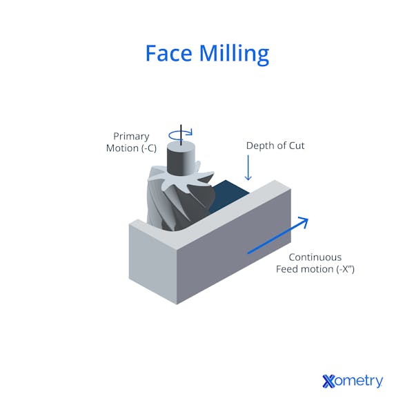
- Face Milling: This cuts material to create a surface perpendicular to the rotating axis of the cutter.
- Angular Milling: This method removes material from a flat surface of the workpiece at an angle.
- Form Milling: This also cuts material, but this time to make irregular surfaces (i.e., curves).
- Gang Milling: This method is able to ramp up the rate of production as it uses two cutters, sometimes more, to cut the material.

Equipment Used in CNC Milling
To successfully carry out this process, a few different pieces of equipment that all work together are needed, and we list these below:
- A worktable to hold the piece steady during machining
- A saddle that’s under the worktable, for extra support and to keep the worktable’s movement parallel to the tool’s rotating axis
- A knee that’s under the saddle to support the worktable and saddle. Its position can be adjusted vertically to accommodate different part thicknesses.
- A spindle is used to hold the cutter and direct its translational and rotational movement.
- An arbor is a shaft that tools are fixed to, and it’s assembled through the spindle.
- A ram (an optional item) is usually used in vertical or angular milling machines to help support the spindle.
- Cutting tools such as end mills.
- The interface (at least a screen and keyboard) is how the operator communicates with the computer that’s controlling the CNC machine.
The Downsides of Using CNC Milling
CNC milling can be used to create parts from a wide array of materials, including metals, plastics and elastomers, ceramics, and composites. Because of this, CNC milling is a highly versatile manufacturing process that can be used to fabricate seemingly any part — with limitations. One of these it’s high cost, even for the simplest machine. For more technologically advanced machines, you can expect a steeper investment.
The machine will also dictate the size of the part you can make, and the part’s shape and any details will depend on the equipment’s capabilities. Recessed details on the part’s surface, like undercuts, will need specialized tools, and sometimes multi-axis equipment, which is also pricey. Also, the success of the process depends on the abilities of the operator; if tools and programs aren’t set up correctly, you could end up with unusable parts and waste.
Xometry's CNC Milling Services
Xometry offers custom CNC milling for a wide range of materials and industries. With 3-axis, 4-axis, and 5-axis milling machines, Xometry can complete rapid prototyping, tooling, and end-use production for your product.
Xometry provides a wide range of manufacturing capabilities including CNC machining, 3D printing, injection molding, laser cutting, and sheet metal fabrication. Get your instant quote today.
Disclaimer
The content appearing on this webpage is for informational purposes only. Xometry makes no representation or warranty of any kind, be it expressed or implied, as to the accuracy, completeness, or validity of the information. Any performance parameters, geometric tolerances, specific design features, quality and types of materials, or processes should not be inferred to represent what will be delivered by third-party suppliers or manufacturers through Xometry’s network. Buyers seeking quotes for parts are responsible for defining the specific requirements for those parts. Please refer to our terms and conditions for more information.


